In the last update, I made some hardware changes and implemented ROS nodes for each part. Except the odometry. Since the hall-effect sensor I had operated on 5 volts and I did not have a voltage level shifter on hand, I decided to use the Arduino Nano (which I was already using for the NeoPixel LEDs that I added for status indication). So the idea is that the sensor sends signals to the Arduino hardware interrupt, which updates a counter, computes the RPM and then the velocity for each time interval, which is sent to the Jetson Nano using the ROSSerial package. The Jetson Nano then uses this linear speed and the servo angle to compute the complete odometry of the car. In this update, I implemented only the first half - computing the linear speed and sending/receiving it at the Jetson Nano. Here are the steps:
Hardware setup
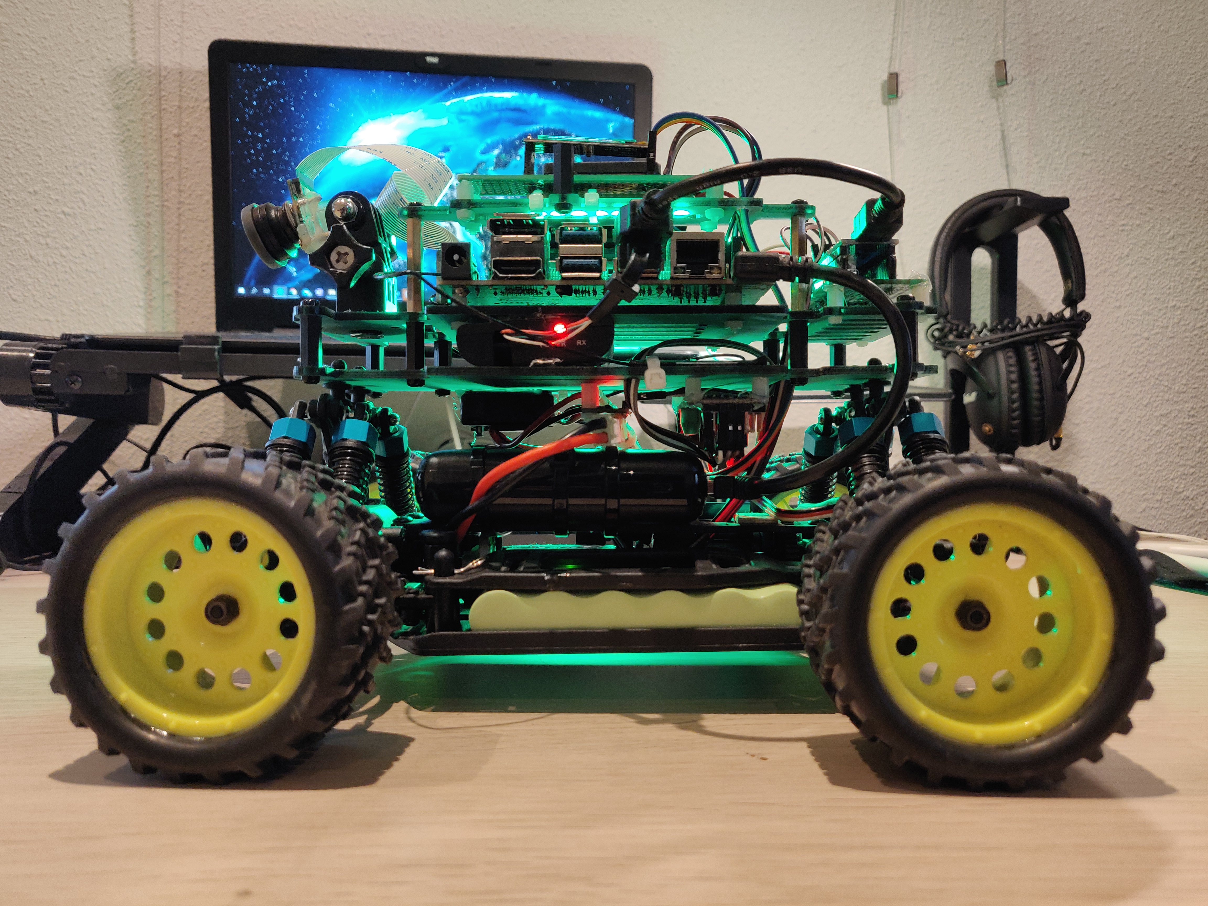
The hardware involves 5 parts: 1 hall effect sensor (I used a cheap one I bought online), 3 3D printed parts (I got mine from here), and some strong neodymium magnets. The 3D printed parts involve a disk with 6 holes (for 6 magnets), a clip to attach it to the main drive shaft and a clip for the hall effect sensor. The installation and setup is very similar to the tutorial made by Tawn Kramer here. The changes can be seen in the photo below:
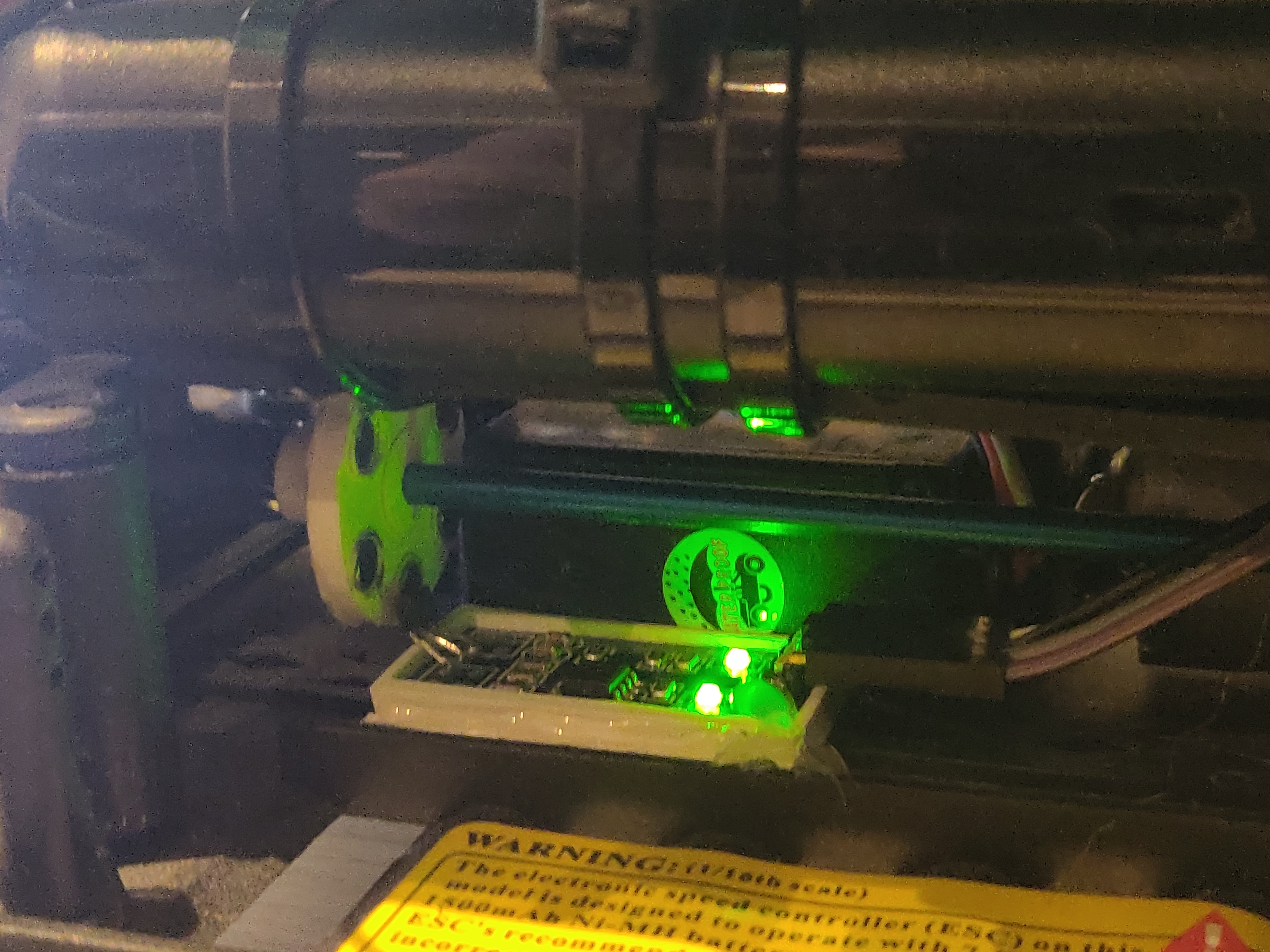
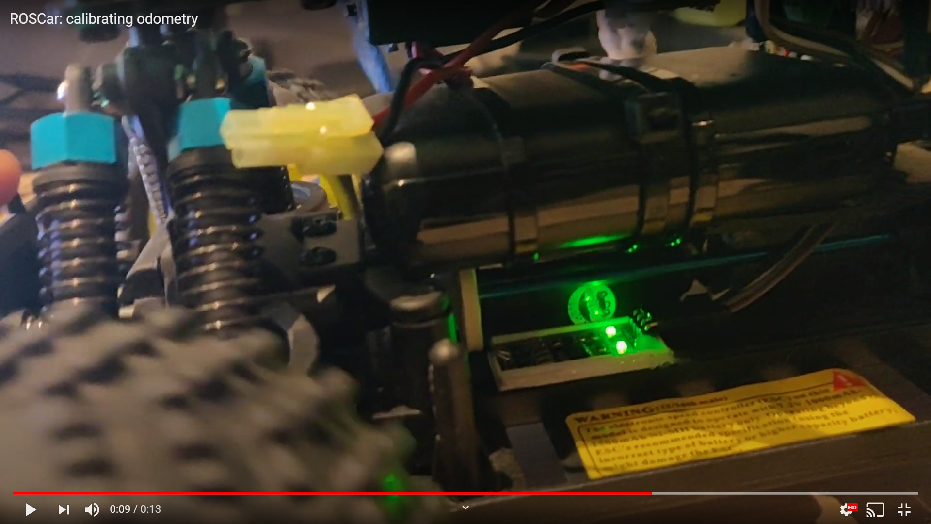
The installation was tested by wiring the 5v and ground pins of the hall-effect sensor to the Arduino’s pins and checking the LED to see if the distance between the sensor and each magnet is okay. Once verified, the digital output pin of the sensor is wired to digital pin 2 (hardware interrupt pin) on the Arduino Nano. A video of this is below:
Arduino Nano / ROSSerial
On the Arduino, the first task is to read and compute the speed. For this, I used an interrupt callback function which increments a counter variable everytime a rising edge is sensed by the hardware interrupt. In the main loop of the code, the counter value is read every second, using which the number of rotations per minute can be calculated. The ratio between the RPM and the linear speed was measured by moving the car along a known straight line and measuring the linear distance travelled vs the number of rotations counted. I did this test multiple times and averaged the results.
Next, I used this example tutorial for a simple publisher to publish the computed speed via ROSSerial to the Jetson Nano. I used the std_msgs/Float64 data type instead of the string as shown in the tutorial. On the Jetson Nano, one needs to run roscore and in another terminal, the serial_node.py provided by ROSSerial. I simply added this to the launch file so that the serial node is initialized everytime the car is started. This is verified by simply checking the topic list and echoing the particular topic.
In the Arduino code, I made the mistake of not commenting out my serial print commands, which I was using for debugging. This gave me errors since I was using a different baud rate (ROSSerial uses 57600). I also had dynamic memory issues with the Arduino Nano 128p (ATMega128), which meant ROSSerial couldn’t send/receive data correctly. This was resolved by upgrading to the Arduino Nano 328p (ATMega328).
Odometry Node
The odometry node is a simple publisher/subscriber that subscribes to the float value sent by the Arduino, formats it into an odometry message and publishes it. In the future, I want to put this together with the steering angle values and estimate the pose. This can then be fused with the IMU measurements using an extended Kalman filter.
Testing
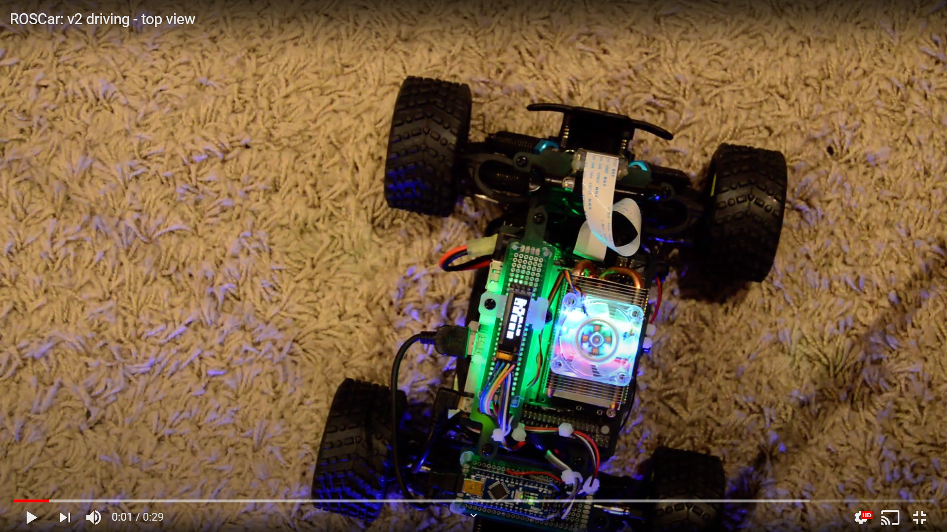
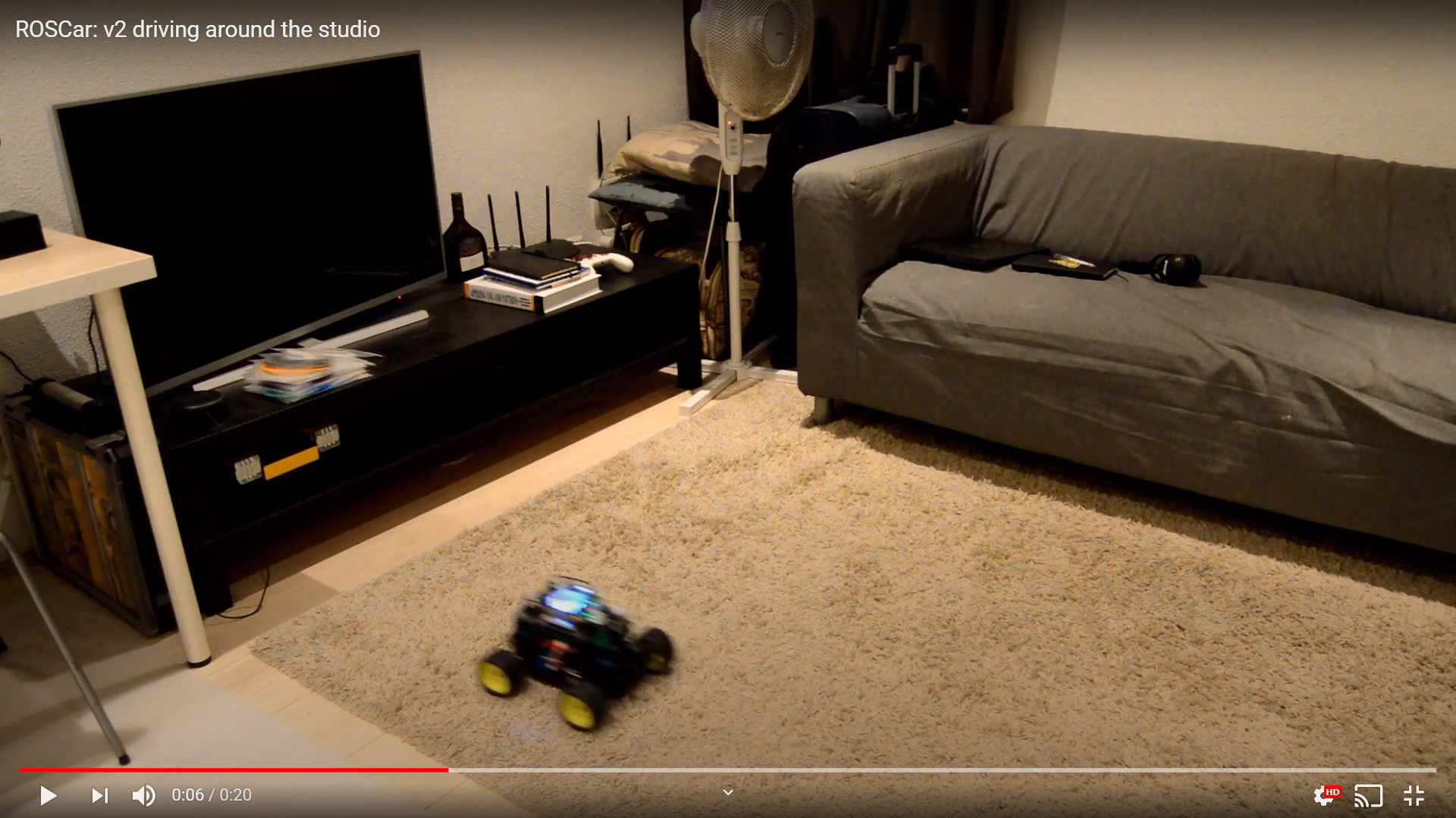
The car was tested by using timed trials over a known distance, while also recording the odometry received on the Jetson Nano. Now since my studio is quite small, and I also did not have a measuring tape, I could only use a 30cm vernier caliper and very low speeds to test the measured speed. I used a tripod and my smartphone to record the tests and measured the actual speed using these recordings. I then checked this with the recorded measurements on the Jetson. The odometry is very accurate, but not very precise but I can can live with it. While I deleted the recordings due to low memory on my phone, here’s a small clip of the test setup (I’m just aimlessly driving around in this one, ~20% throttle).
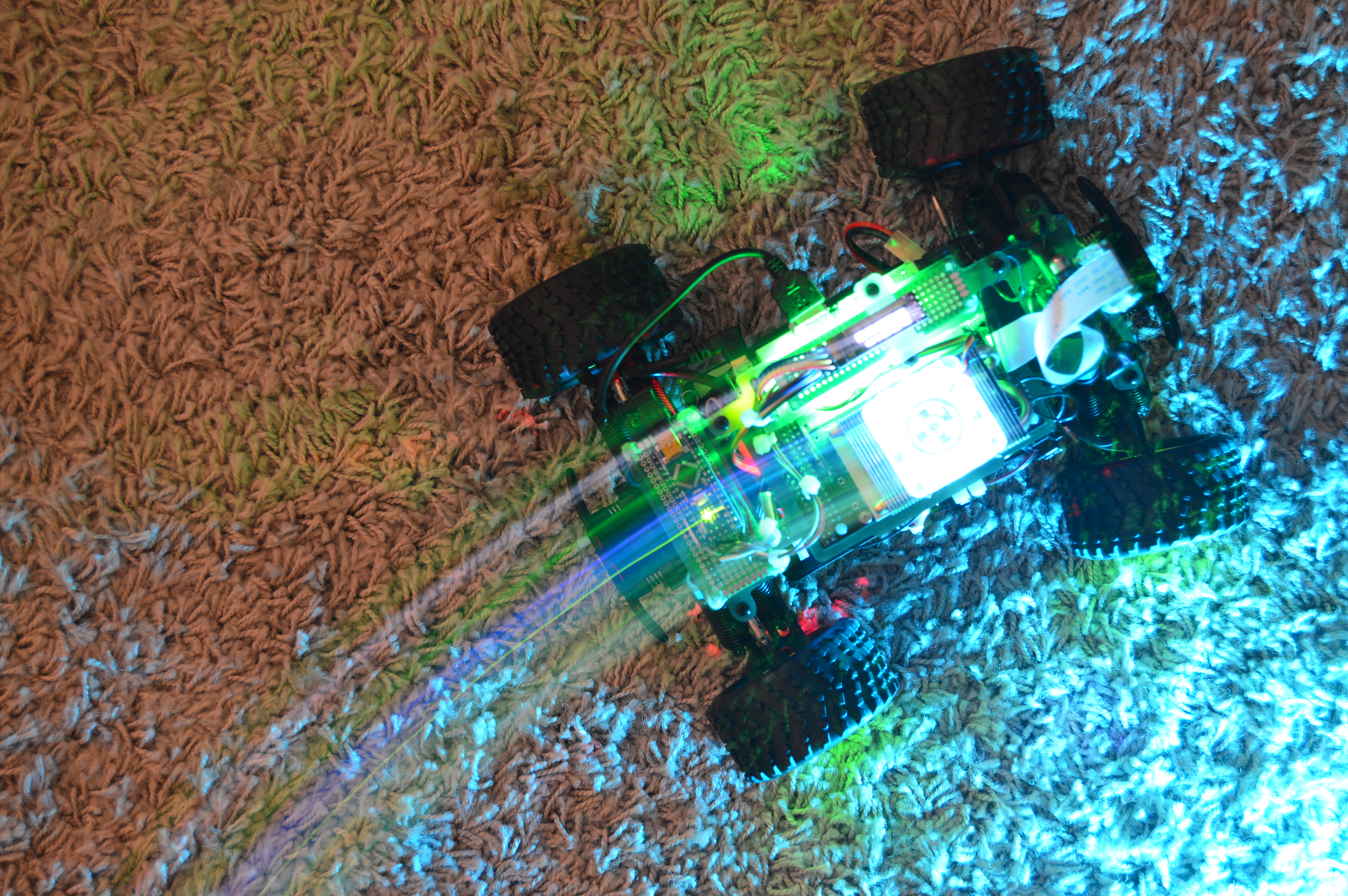
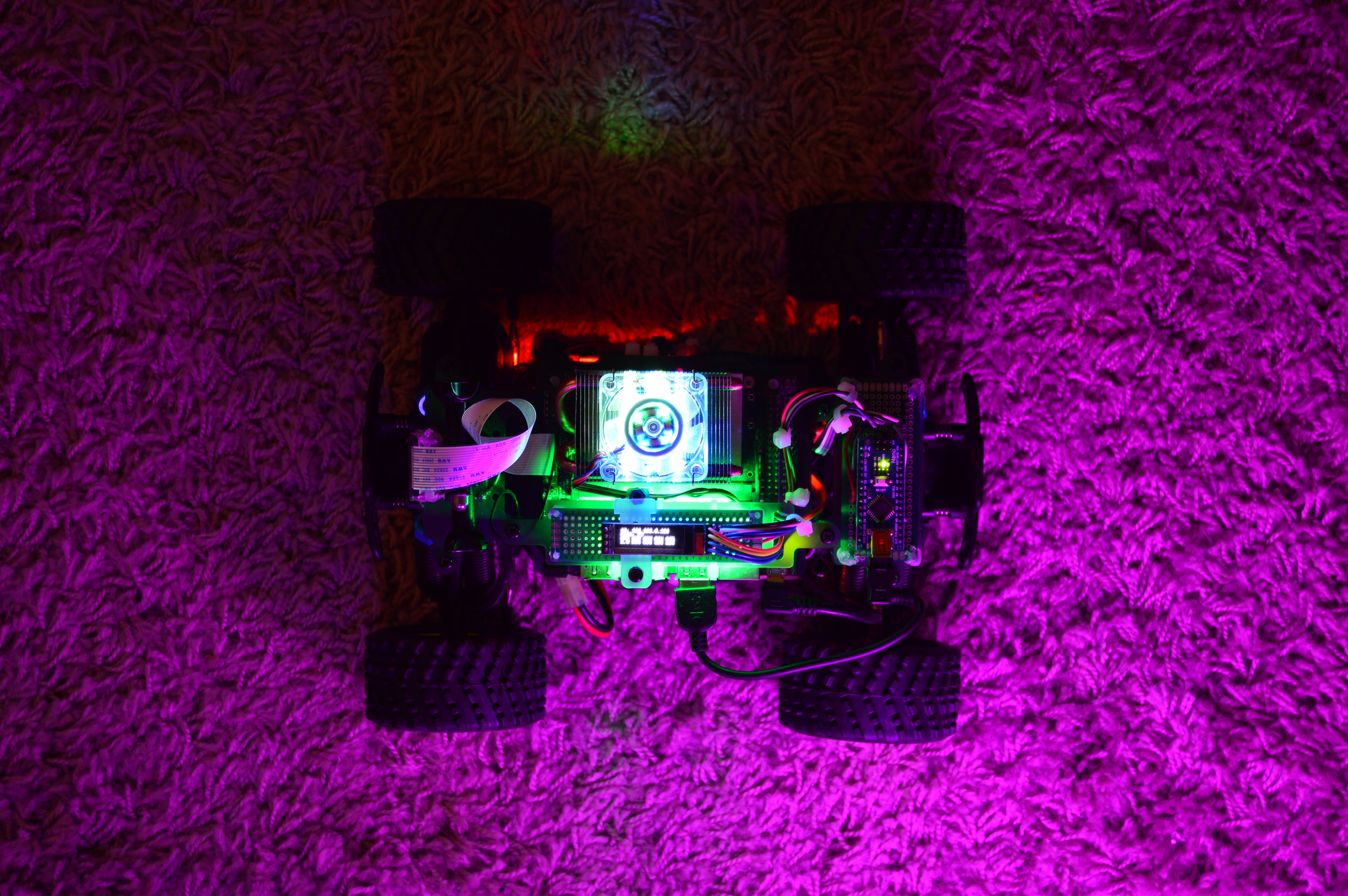
Cool long-exposure photographs
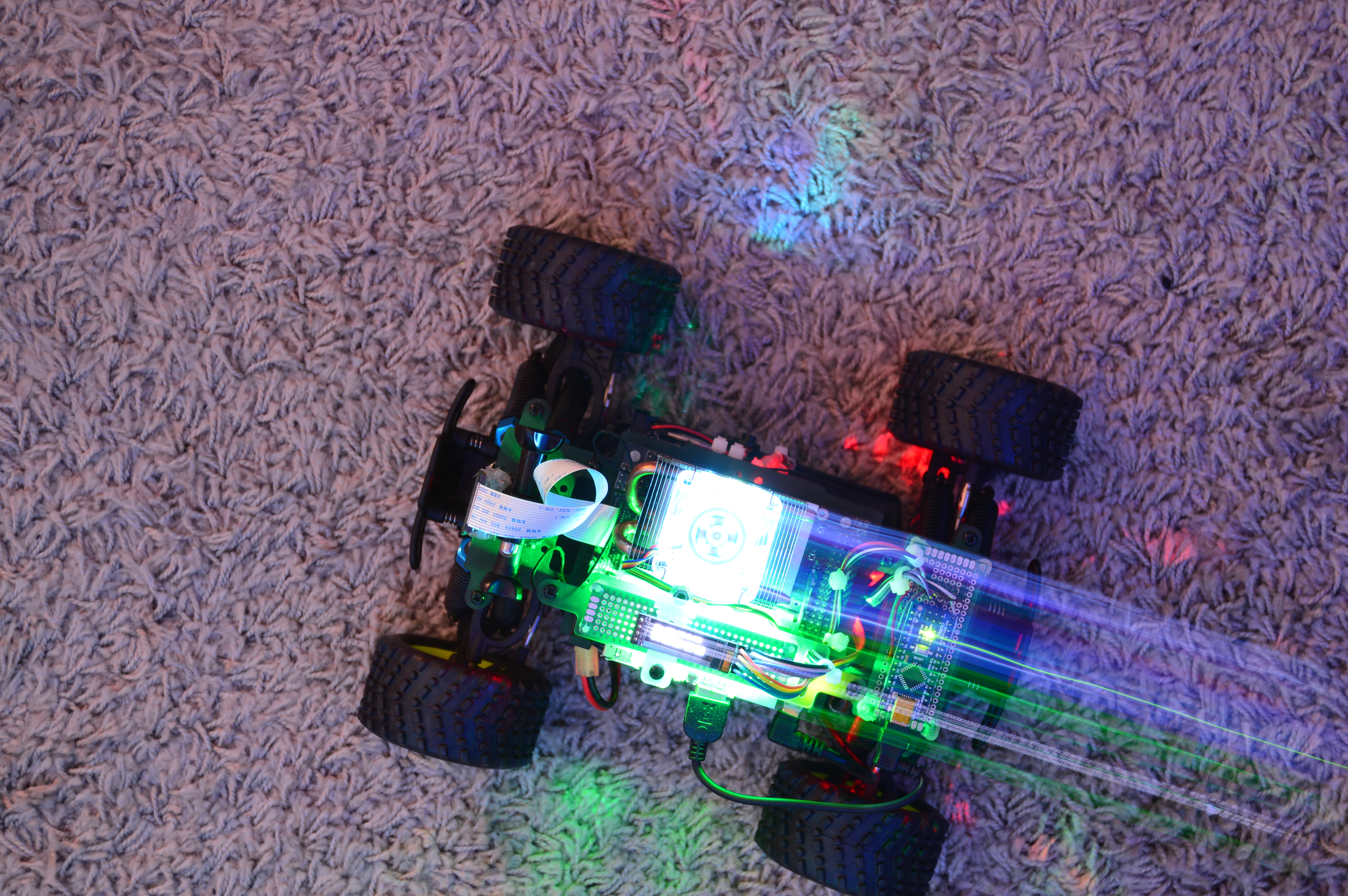
While driving around, I also clicked some long exposure photographs of the car in action. I must confess, for 50% of the time, the car battery was completely out of power and I was basically moving it around with my leg. The photos are still nice though (the Jetson battery, and hence the LEDs were still running).
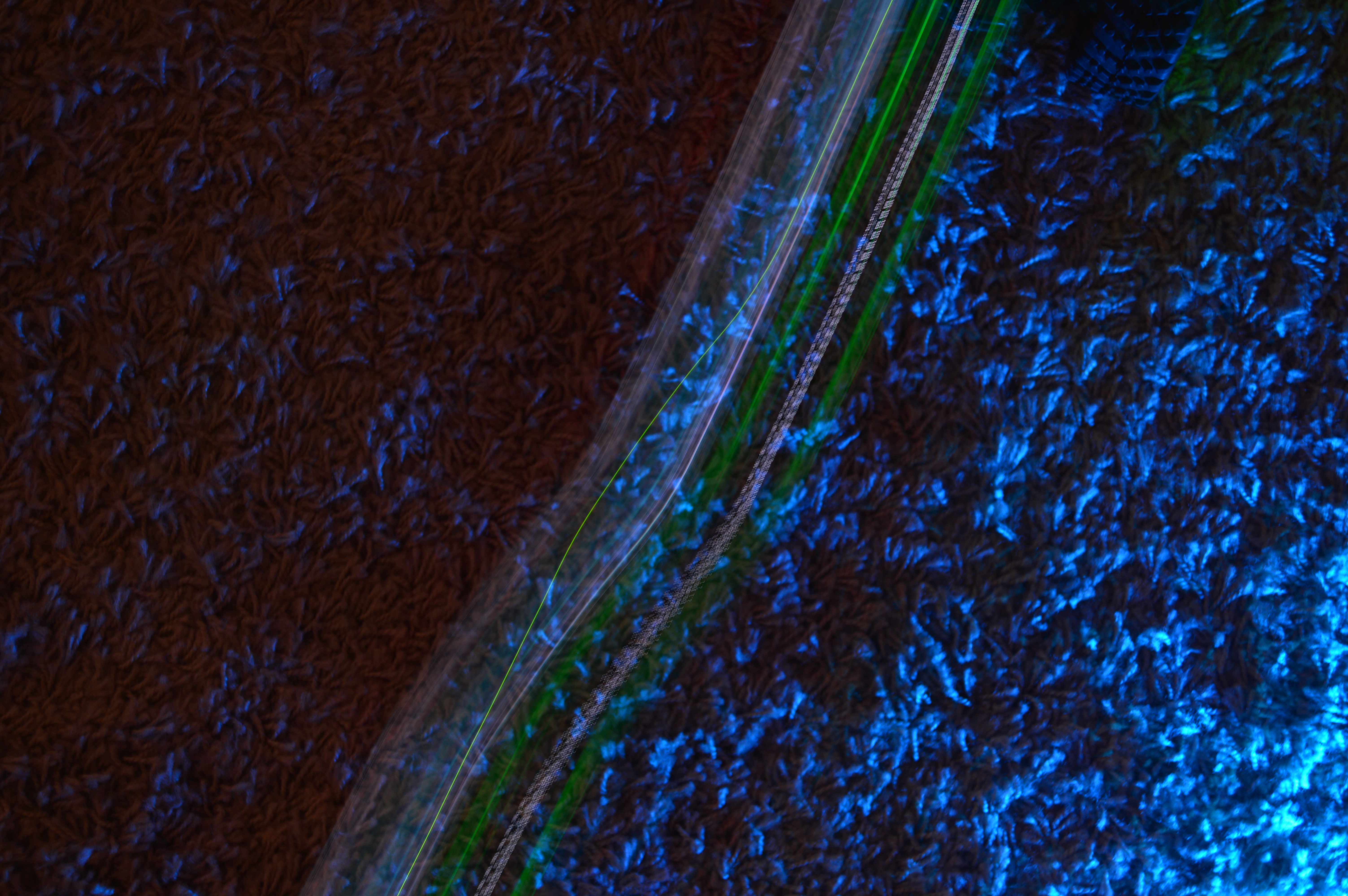
Ground-truth measurements
These photos made me think if this is a potential way of testing the odometry. Theoretically, it sounds great - the camera settings are known, the car can be made to drive for a specific amount of time. If the car and the camera can be triggered at the same time, the resulting photo should show a straight line of the exact distance travelled, just like the photos above. But practically, driving the car along a measuring tape is still the easiest and the most effective way.
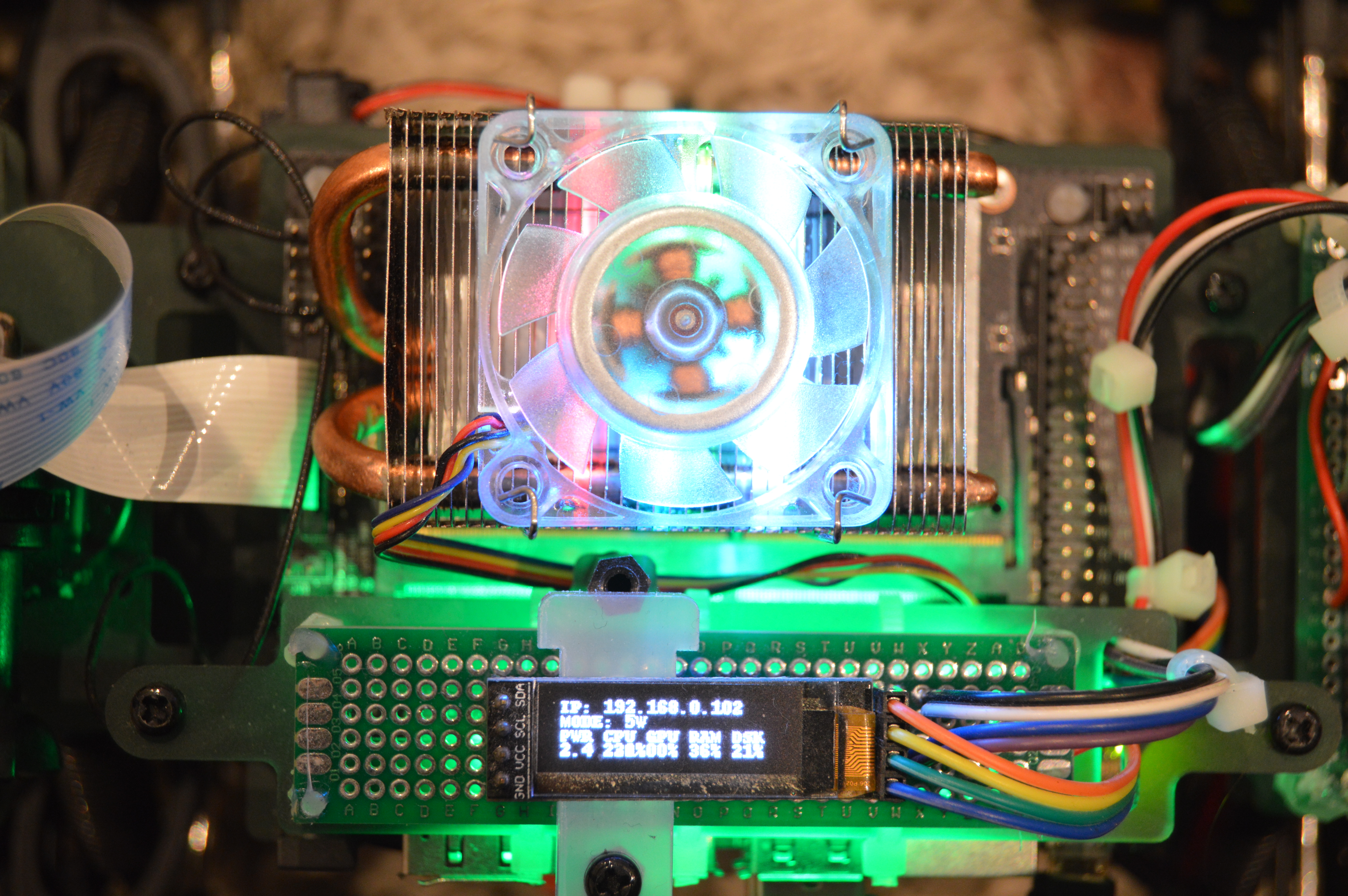
Some hardware changes
I also made some hardware changes along the way. Now that the car is running, I am trying out some machine learning/AI tutorials and experiments. When I run any experiment, I try and have the car’s ROS application running in the background. Since they are all going to be running together on the Jetson Nano when the car is in operation. Sometimes, the Nano gets too hot (it still hasn’t crashed due to overheating, thankfully), so I decided to once-again use the ice cooling tower by S2Pi. Its an extremely efficient cooling system, and keeps the nano cool even without the fan on.
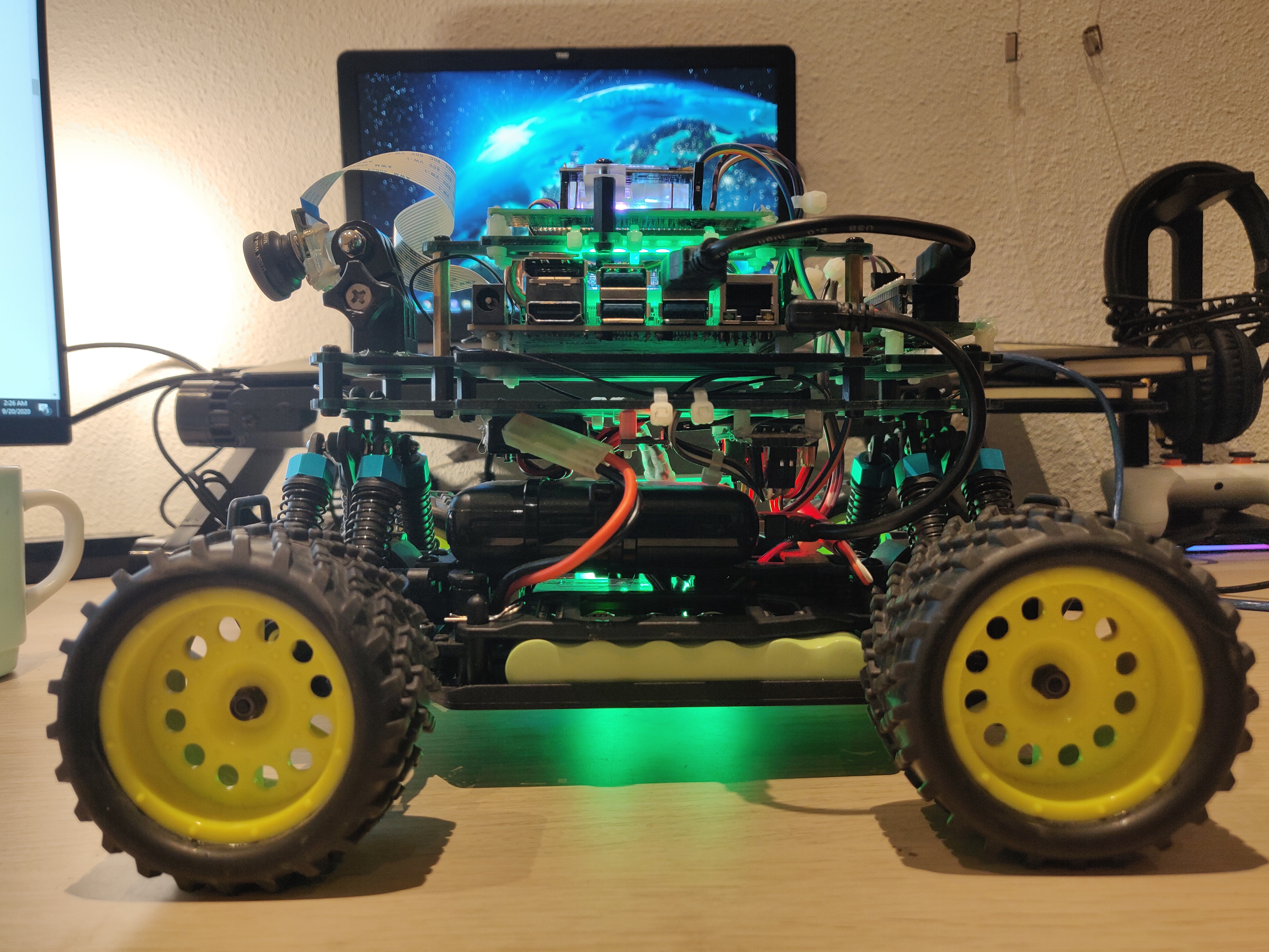
For the second hardware change, I added a spare/random piece of acrylic under the PiOLED screen. Its not fixed completely on both sides, but it does the job.
Finally, my cheap 3rd party sixaxis controller finally died after 8 long years. I remember buying it sometime around 2011-2012 during my bachelor’s in India. I tried to fix it but couldn’t so I salvaged some parts like the joysticks and buttons and threw away the rest. This meant that I could also throw away the bulky receiver and hence replace the plastic standoffs with smaller ones to make the car more compact. Here are some before/after pics:
Before:
After:
For the new controller, I once again went for a 3rd party controller but made sure it came with a small USB dongle.
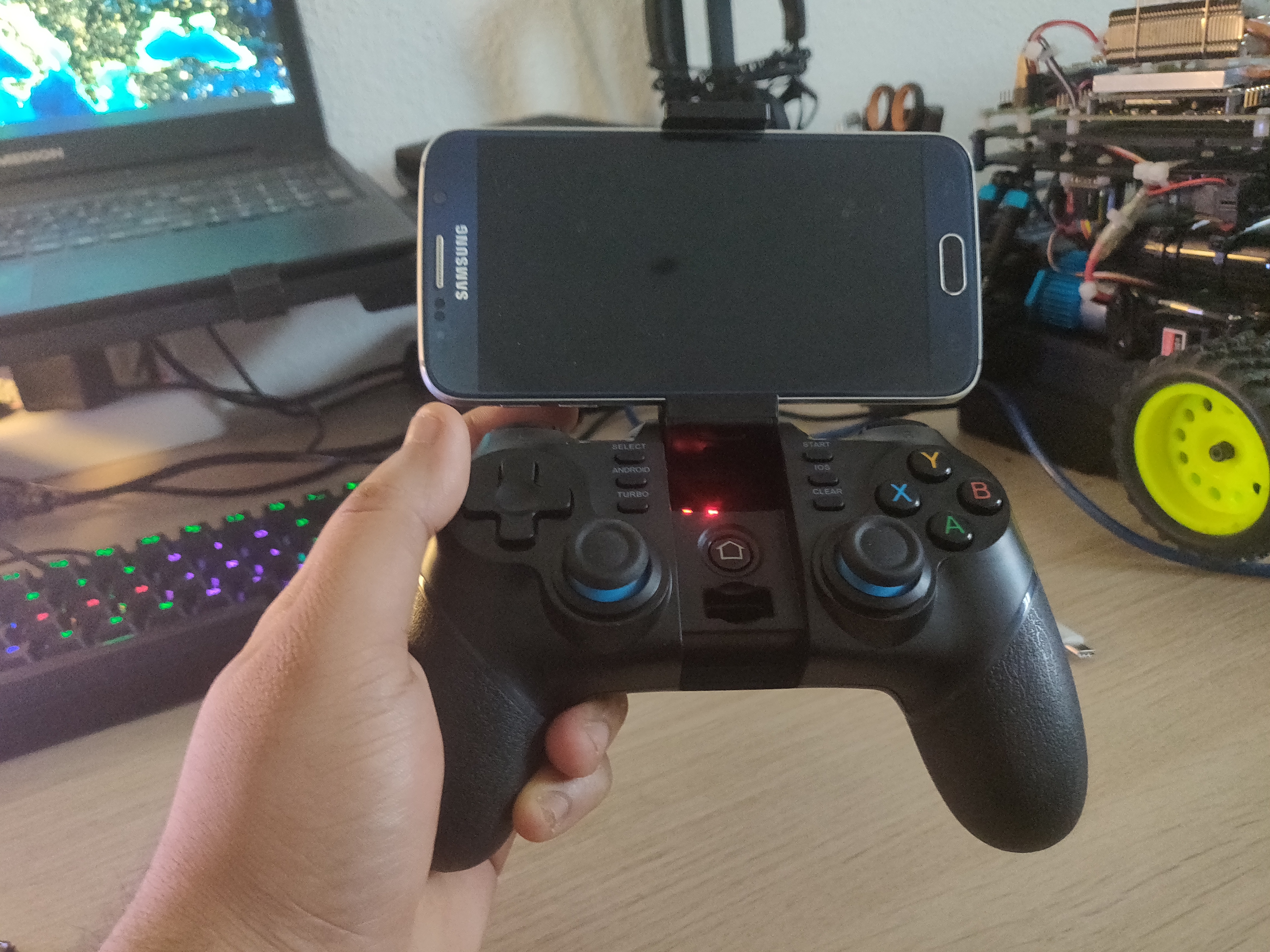
Here’s me driving around my studio:
Plans for the next update
For the next few months, I plan on working entirely on the AI. I have already started off doing experiments with face/object detection, lane detection/following. But I want to also work with concepts such as semantic segmentation and visual positioning. Lastly, I need to try and make this working with ROS. I want to get this done by the end of this year. Let’s wait and see how that goes.