Ever since I read this article about microROS (ROS2 for microcontrollers) and ESP32, I’ve been wanting to implement it myself but I never really got the time. This was because I was working on the DepthAI + OAKD project. But I did manage to buy some components in the meantime - I got 4x N20 DC motors with quadrature encoders from AliExpress, 2x TB6612FNG dual-H-bridge motor drivers (here is an article about TB6612FNG vs L298N), some ESP32 boards (including the DevKit C from the microROS article) and while I was there, I also purchased a Teensy 4.0 (apparently this can also run microROS).
So, when I first got some spare time, I drilled some holes into a proto-board and attached the 4 motors to each corner. I also soldered headers to attach the ESP32 DevKit C. I then soldered headers for the 2 motor driver boards and also soldered the motor’s wires to the proto-board. Next, I took a spare IMU and soldered headers for it on the board. Here’s how it looked like:
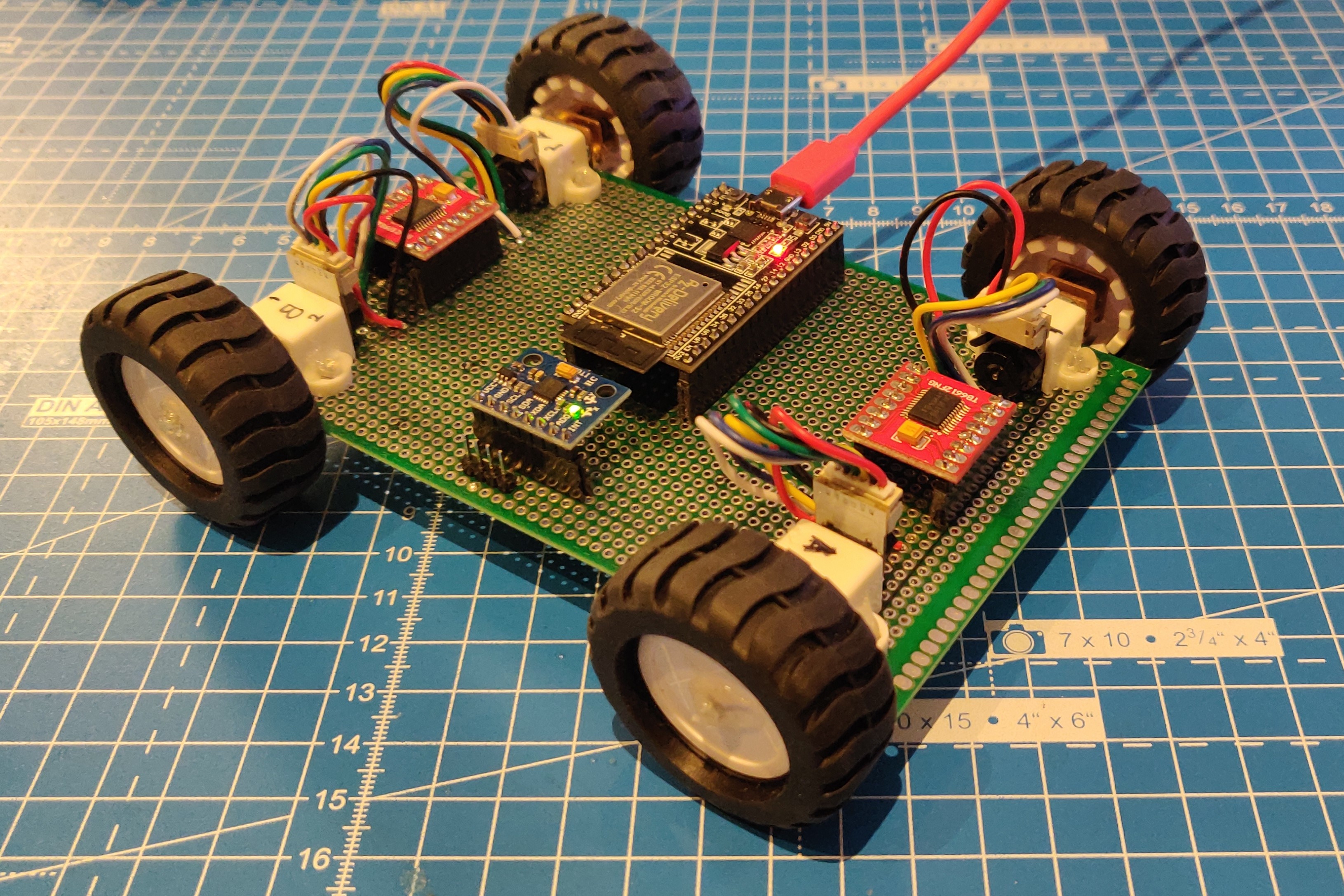
By this time, I was getting some idea of what I want to do with this board/robot - I wanted to implement a motor controller board, with closed loop control using encoder and IMU feedback. I wanted this board to be capable of running up to 4 motors independently which will allow different robot configurations - 4W differential, 2W differential, 4W holonomic with mecannum wheels, 3W holonomic with mecannum wheels or also other robot applications where up to 4 DC motors might be required. I also wanted headers to connect external I2C devices such as a PCA9685 16 channel servo control board.
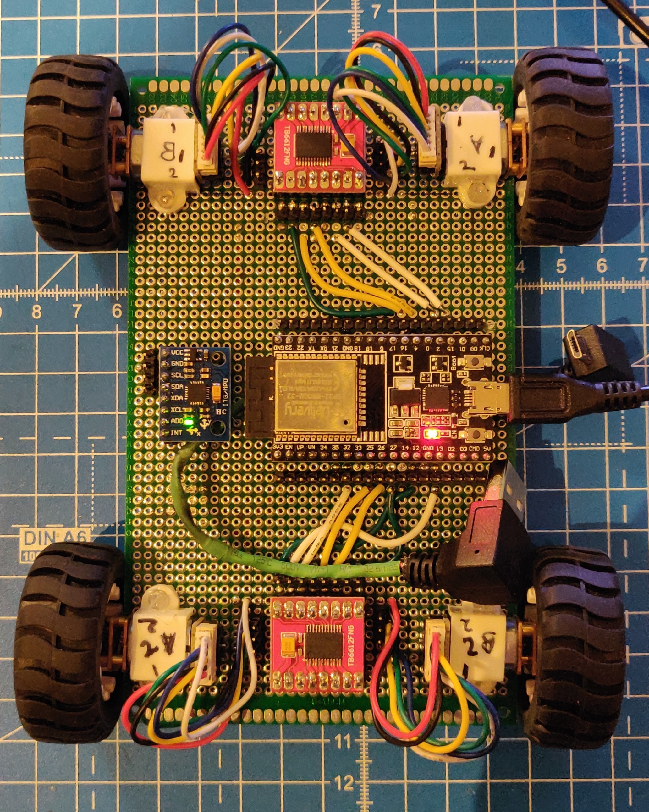
With an idea in place and the basic robot structure already set up, it was time to do the wiring. I first wired all the Vcc and Gnd pins to respective pins on the ESP32 to see if everything was working. Once this was verified, I connected the IMU SDA/SCL pins to the I2C pins of the ESP32, and the IN1/IN2/PWM pins of each motor to digital pins on the ESP32. I then connected the motor +/- pins to respective pins on each motor driver board. Now, everything except the encoders were connected and this can be seen below:
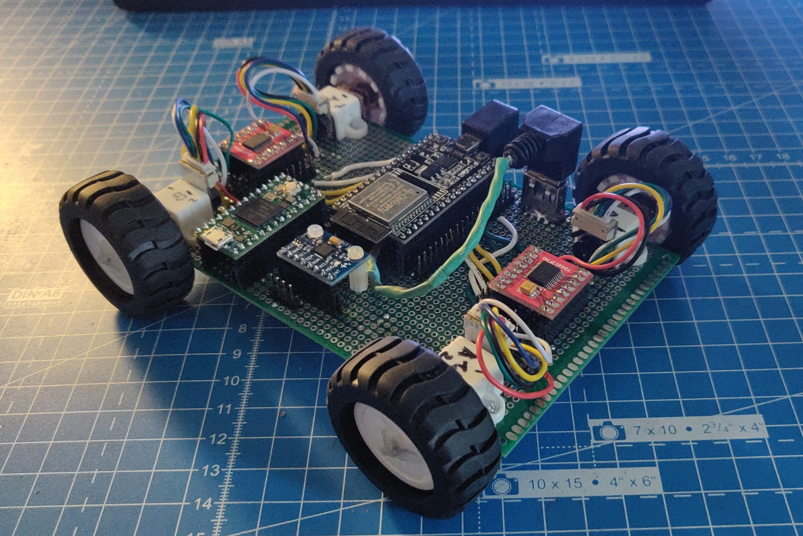
Finally, it was time to connect the encoder pins to the ESP32 board. This is when I realized that I did not have enough pins for each encoder. Since these are quadrature encoders, there are 2 hall effect sensors per motor, which means 8 pins for all 4 motors. This is when I realized that there is space on the board for a Teensy 4.0 and connected the encoders to it. Every digital pin on the Teensy 4.0 is interruptable, so this definitely solved my problem. This is how it looked like:
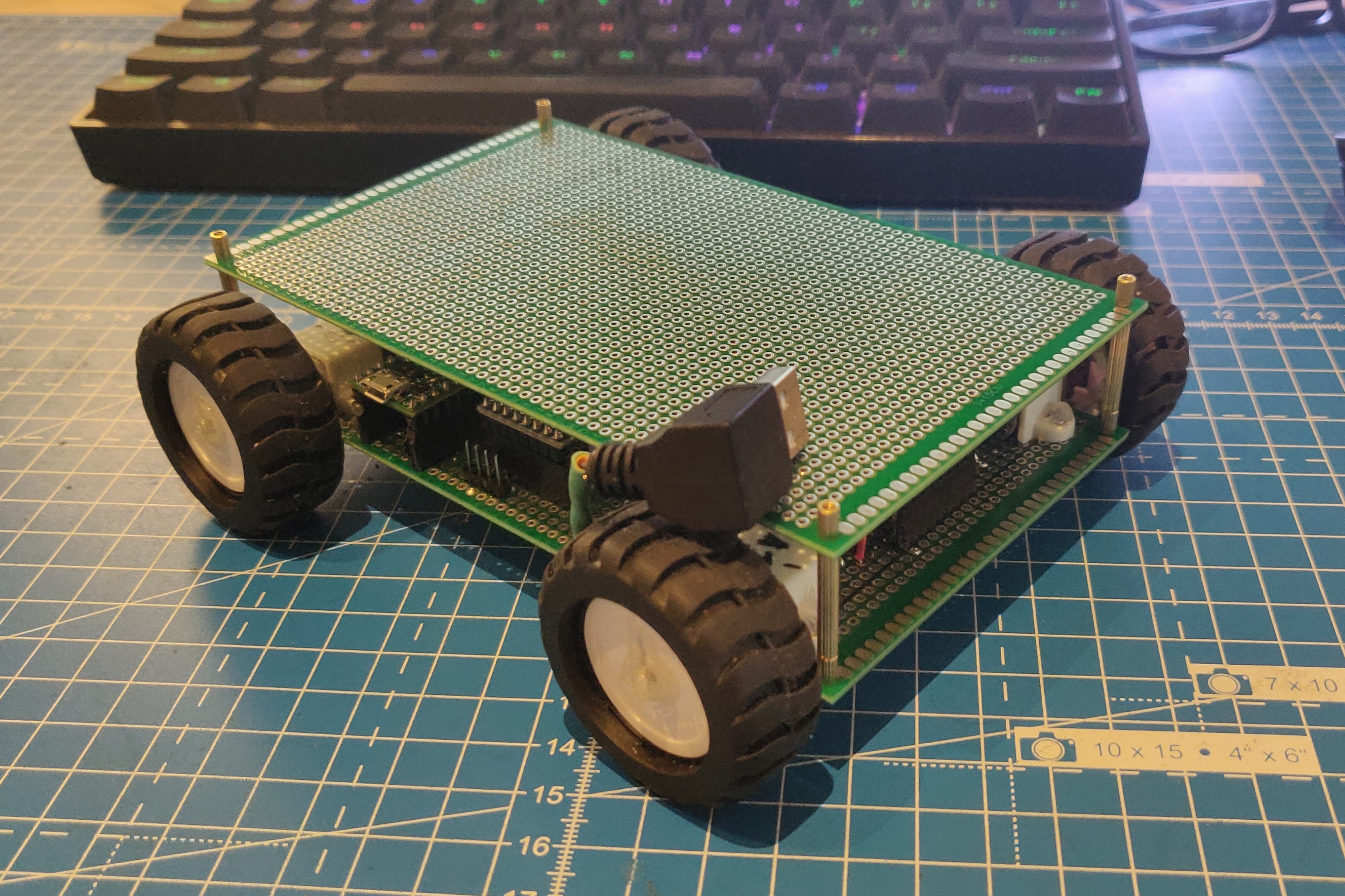
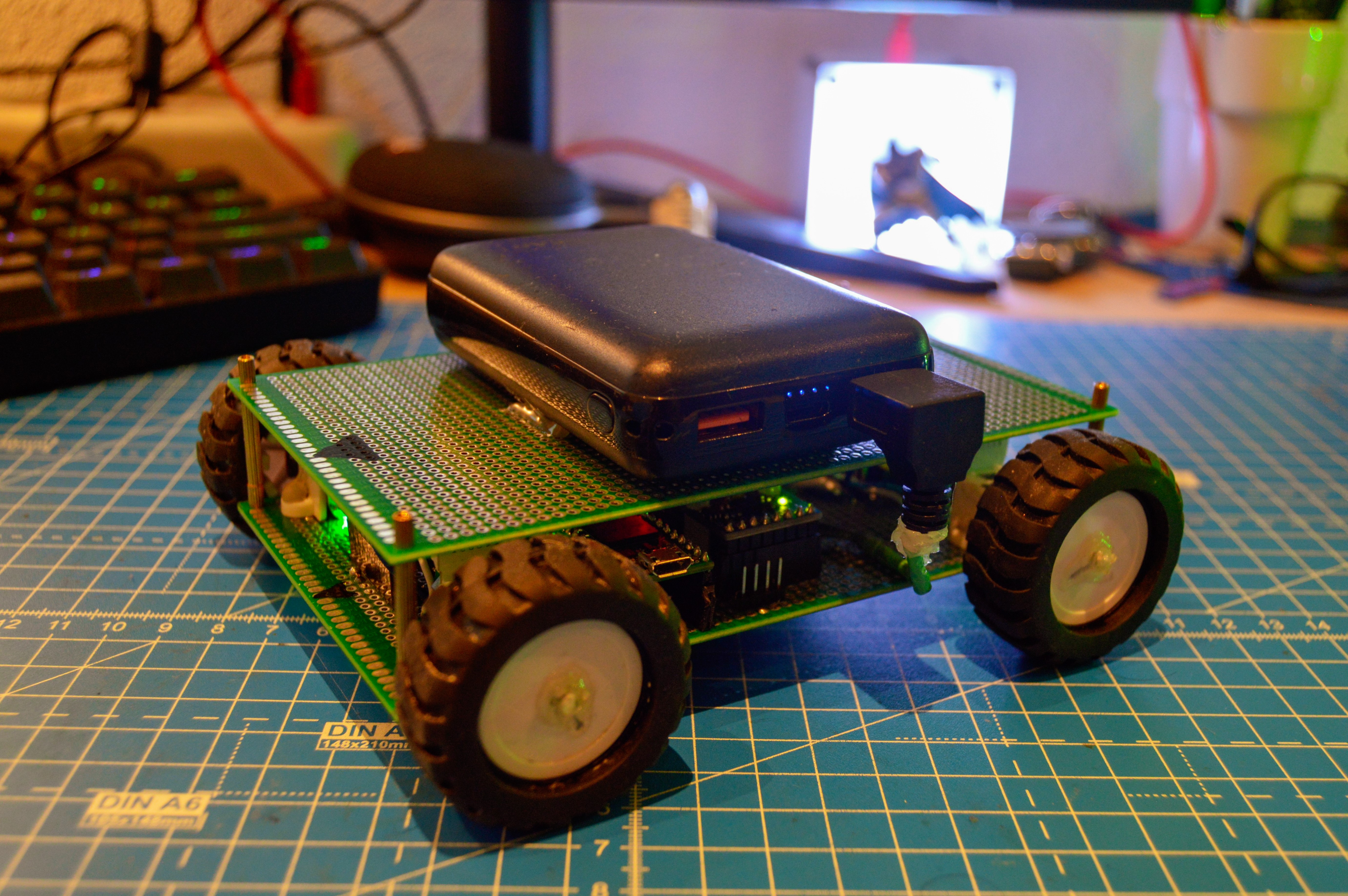
To top it all off, I took another PCB of the same size and attached it using PCB spacers like seen in the image below. This let me make a platform where I could place and USB power bank. There is also enough space available to solder in additional features such as head/tail lights or other sensors. With the Teensy 4.0, I also have enough IO pins available. This is how the final robot looks like:
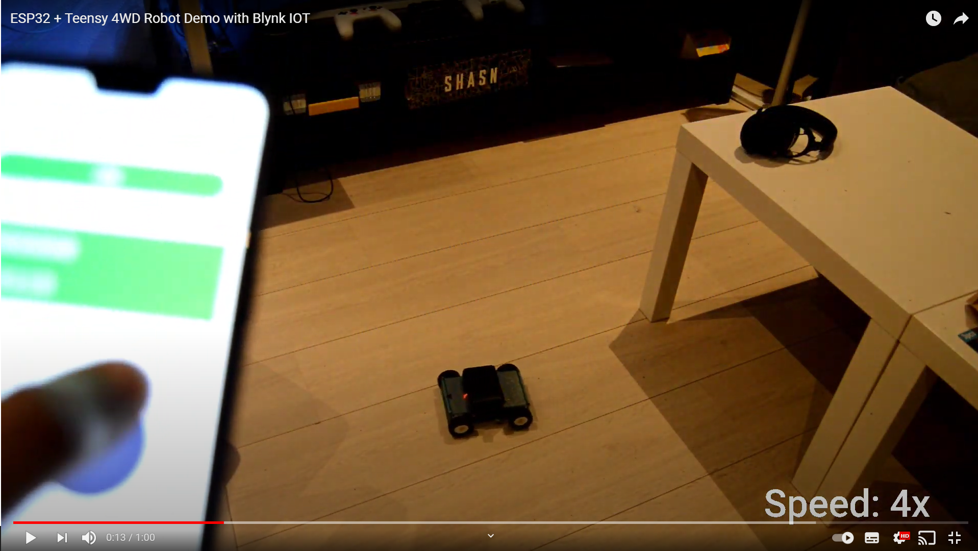
Now it was time to program it. I started with Blynk IOT, an application I’ve used before in the Pinguino notification lamp. This app lets me build a GUI using drag-drop elements and using their web interface, and Arduino libraries, I can stream these GUI inputs to any arduino based device (this includes both ESP32 and Teensy 4.0). Using this app, I was able to make a joystick controller to provide linear/angular and scaling commands to the ESP32, which then controls the PWM output of each motor using differential steering. In the following video, I control the robot using this app and drive it around my studio, have a look:
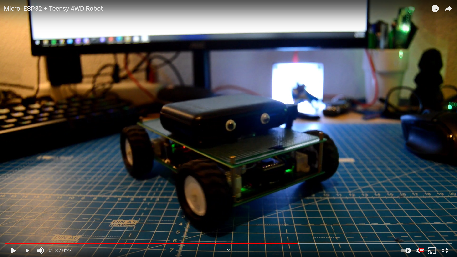
Finally, no robot is complete without some personality, so I added some googly eyes.
For now, this application is solely programmed on the ESP32 using the Arduino IDE. It controls the motors in an open loop way since the encoder interrupts are not yet programmed. This would be my first step. The next step would be to make the teensy talk to the ESP32 over serial/I2C/SPI/CAN…there are multiple options available. This would close the loop. The final step would be to fuse the IMU measurements to correct the encoder estimates, and then port everything to micro-ROS.
The next goal of this new project is to design a PCB to integrate all these things. I plan on using a single Teensy 4.1 instead of an ESP32 and Teensy 4.0. The 4.1 has enough pins for 4 motors, 4 quadrature encoders, I2C, Serial/UART, Ethernet, CAN, SPI and even more GPIO to spare. It also has an SD card slot where can record and store the robot trajectories once the encoder/IMU functionality is programmed. More on this soon.