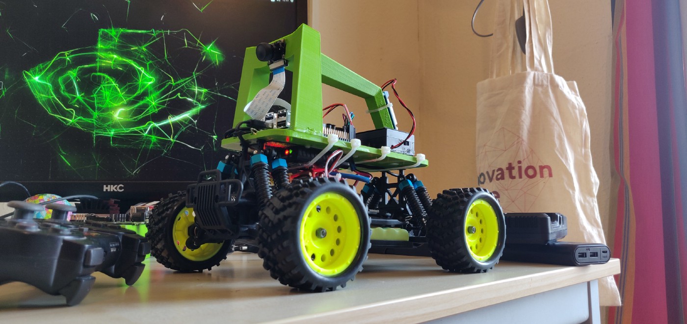
The parts have arrived! At least, most of them. Most surprisingly, the car from Hong Kong arrived a day before the servo driver which I ordered from Amazon Germany. Once again, I used the Donkeycar documentation to build the car. However, I made a few tweaks…
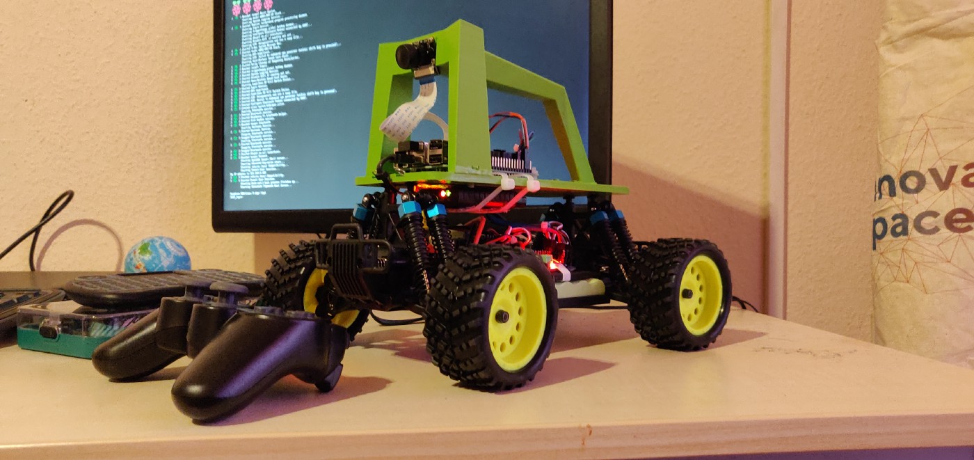
Roll-cage super-glued to base-plate:
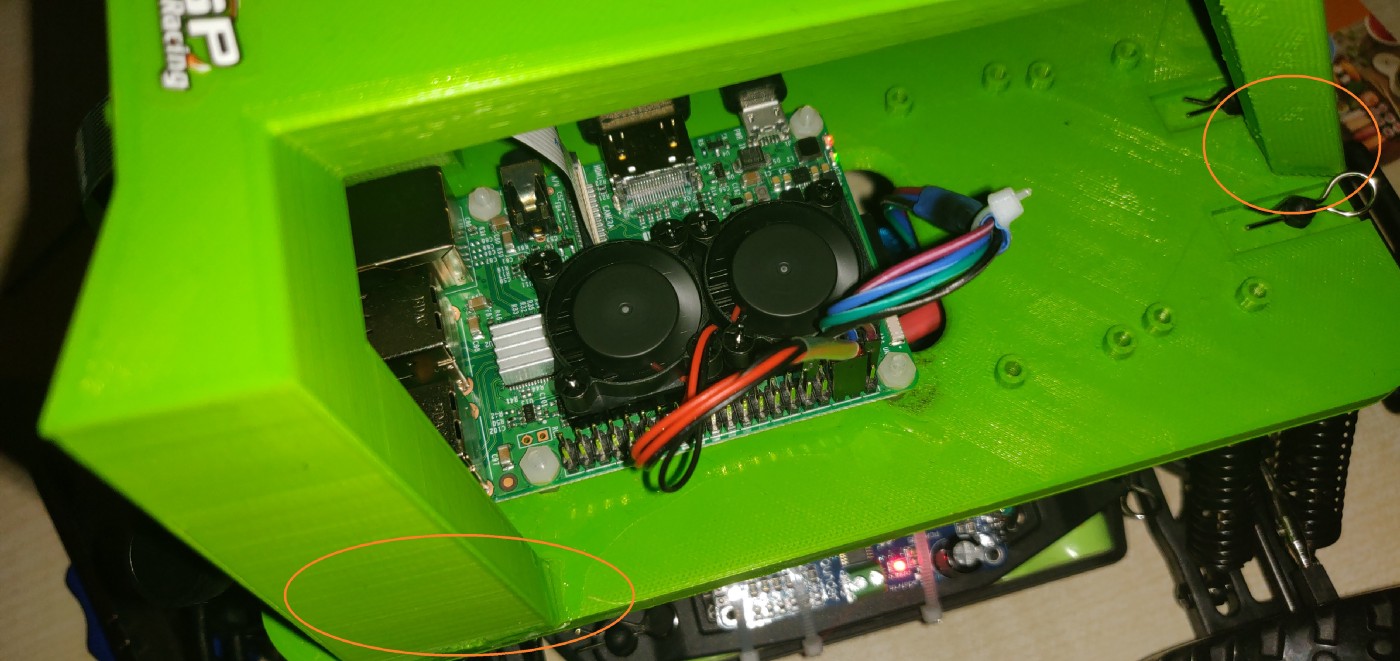
I did not have the right tools to clean up the 3D printed roll-cage. Also, it was getting surprisingly difficult to find the necessary nuts/bolts in shops around me. So, I went ahead and recklessly super-glued the roll-cage to the base-plate. It is very sturdy and I am not finding it difficult to access the electronics on top of the base plate, so its good for now.
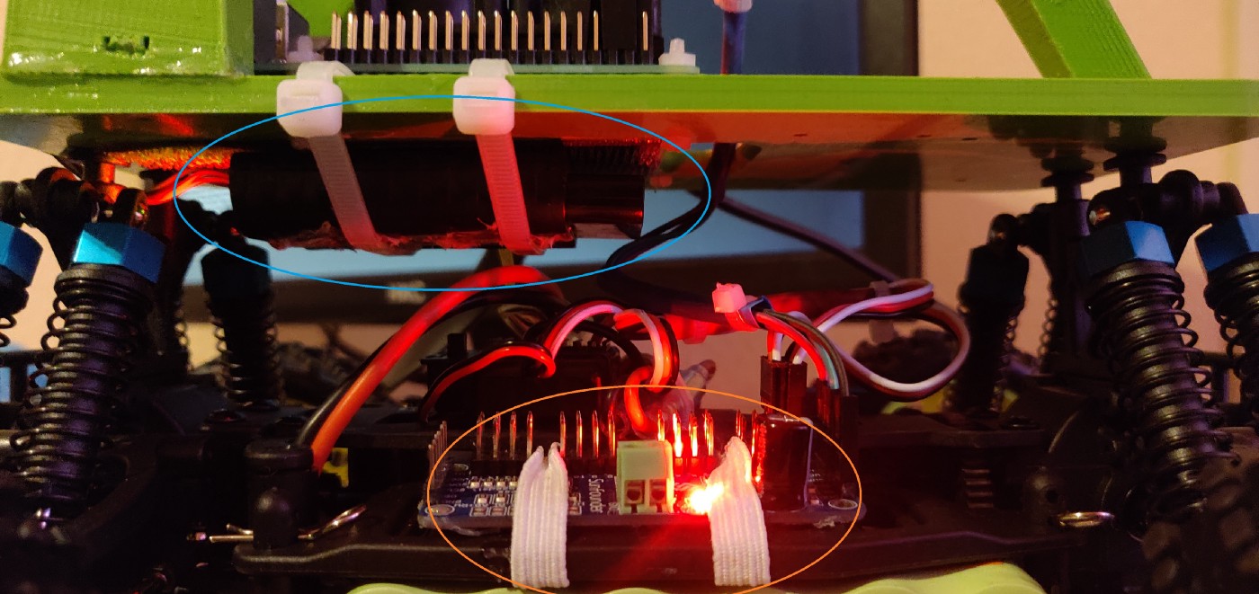
RedGear USB Gamepad with the receiver connected to RPi via USB and attached under the base-plate:
The recommended method in the documentation is to use a standard Sony PS3/PS4 or Xbox controller connected via Bluetooth. More details can be found here. This method allows the RPi to connect to the Bluetooth controller and then read six-axis data at /dev/inputs/js0. However, I had a 3rd party wireless controller (RedGear Wireless Controller for PS2/PS3/PC) that sends data to /dev/inputs/js0 without any additional installation. However, the receiver is big and I had to attach it under the base-plate using zip-ties. I need to map the receiver buttons to the car controls, I will write more about this in the next post.
Servo driver attached to the car body:
In order to future-proof my car, I decided to divide the entire system into 2 parts: the body and the brain. The body contains everything necessary to drive the car (and sense its movement - I plan on adding an IMU here) and the brain involves the base-plate/roll-cage and everything connected to it (RPi, Camera). This essentially lets me remove only the top part of the car and replace it with a different processor/camera/roll-cage (an NVidia Jetson Nano based system for example) while retaining the same servo driver and IMU.
Update:
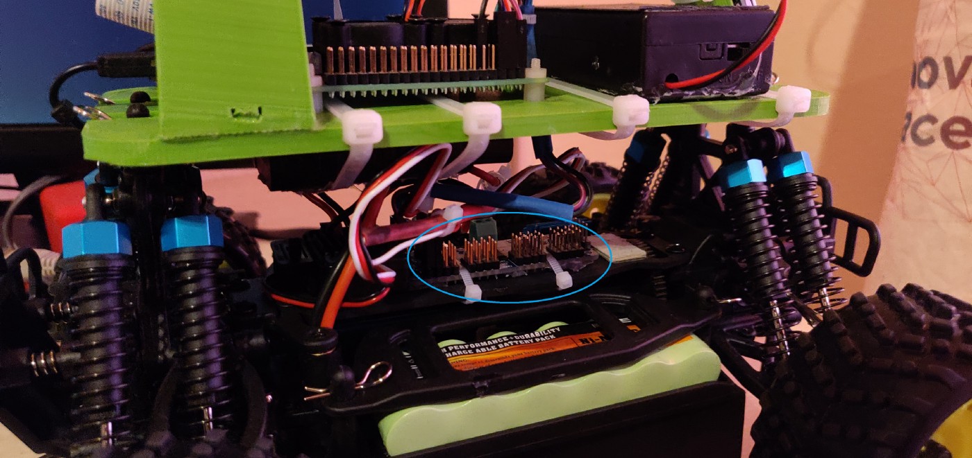
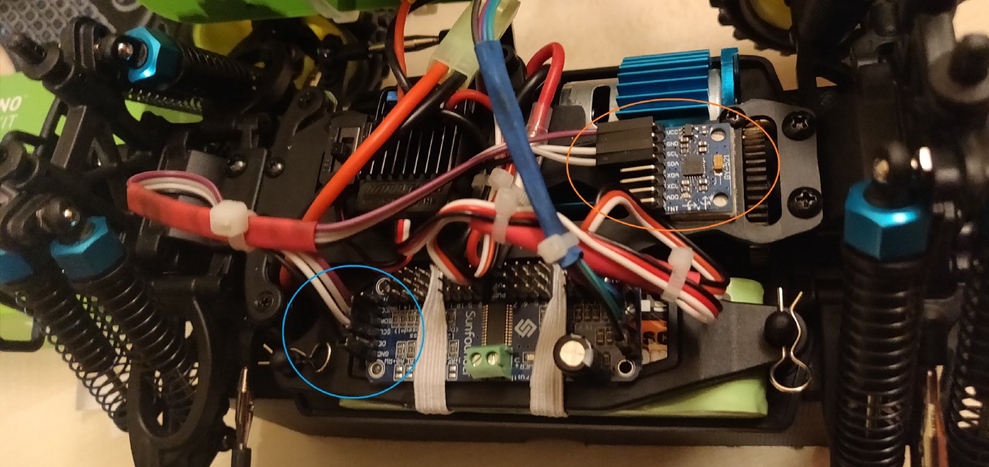
1. Adding an IMU to the car body: Since there is no method of inertial odometry at the moment, I plan on adding an MPU 6050 IMU to the car body. I have currently ordered it from Amazon Germany and its on its way. I still haven’t exactly decided the exact position I will be attaching the IMU. I will be writing a complete post about the IMU, more updates then.
I decided to attach it near the ESC on the car body - I used a cardboard base and double-sided tape. Then, I connected the VCC, GND, SCA and SCL pins to the servo driver, for it to read data from the I2C chain. The orientation is: -ve x towards the front of the car and +ve y on the right side. I’ll be making necessary changes in the code, updates in the next post.
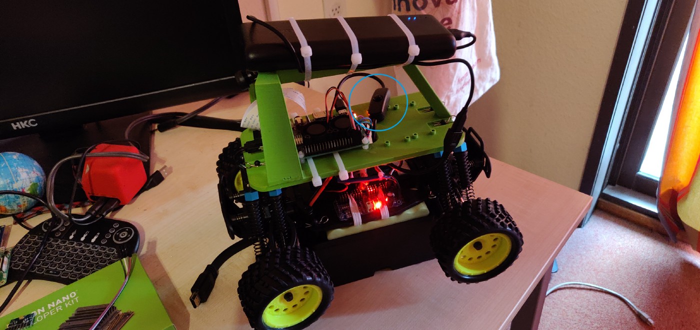
2. Attaching the portable power bank to the handle: The power bank that I have right now is too big to fit under the base-plate. It does fit without the external casing, but it still blocks the hole for the electronics. A new power bank is ordered, will be zip-tied to the handle.
I ordered the Anker PowerCore external battery from Amazon Germany. Attached it to the roll-cage handle with zip-ties.
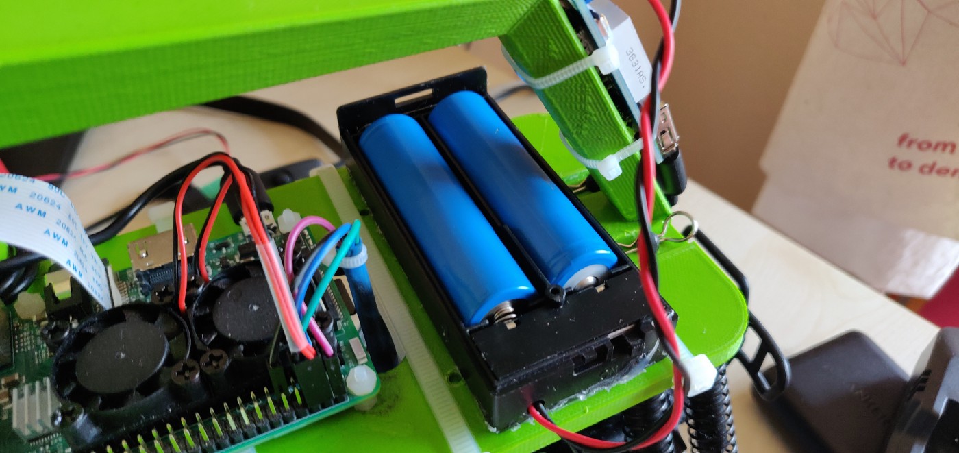
However, when I first drove the car, it jerked a lot when changing throttle directions - because of the really heavy power bank. I decided to replace it with a 2x 18650 LiPo battery pack which I salvaged from an earlier robot. This was connected to a 5V voltage converter, which powers the Pi via USB.
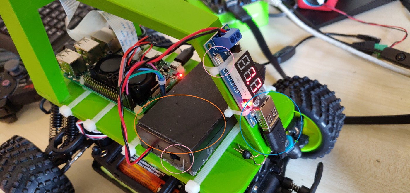
The only disadvantage here, other than the different battery duration, is that the batteries need to be removed to be charged. It is not that big of a deal since the batteries are easily accessible
3. Raspberry Pi power button: Its a shame that the Raspberry Pi does not have a power button. And it is not only me, but there are also a lot of people who are annoyed by this. There are some alternatives out there to either make a power button using a push-switch or use a USB cable with a switch. I tried the latter but somehow, it did not work. I haven’t tested the power output yet, but the cable works otherwise, just not with the Pi. More research needs to be done, updates in the next post.
The USB switch which I used earlier with the power-bank was no longer needed since the new battery pack has its own on-off switch. In addition, the voltage converter has a power button as well, which cuts the connection to the Pi and still allows you to read the battery voltage levels.
With all remaining tasks complete, the robot hardware is now finally done. Next task is to configure and map a 3rd party game controller and to finally drive the car around.