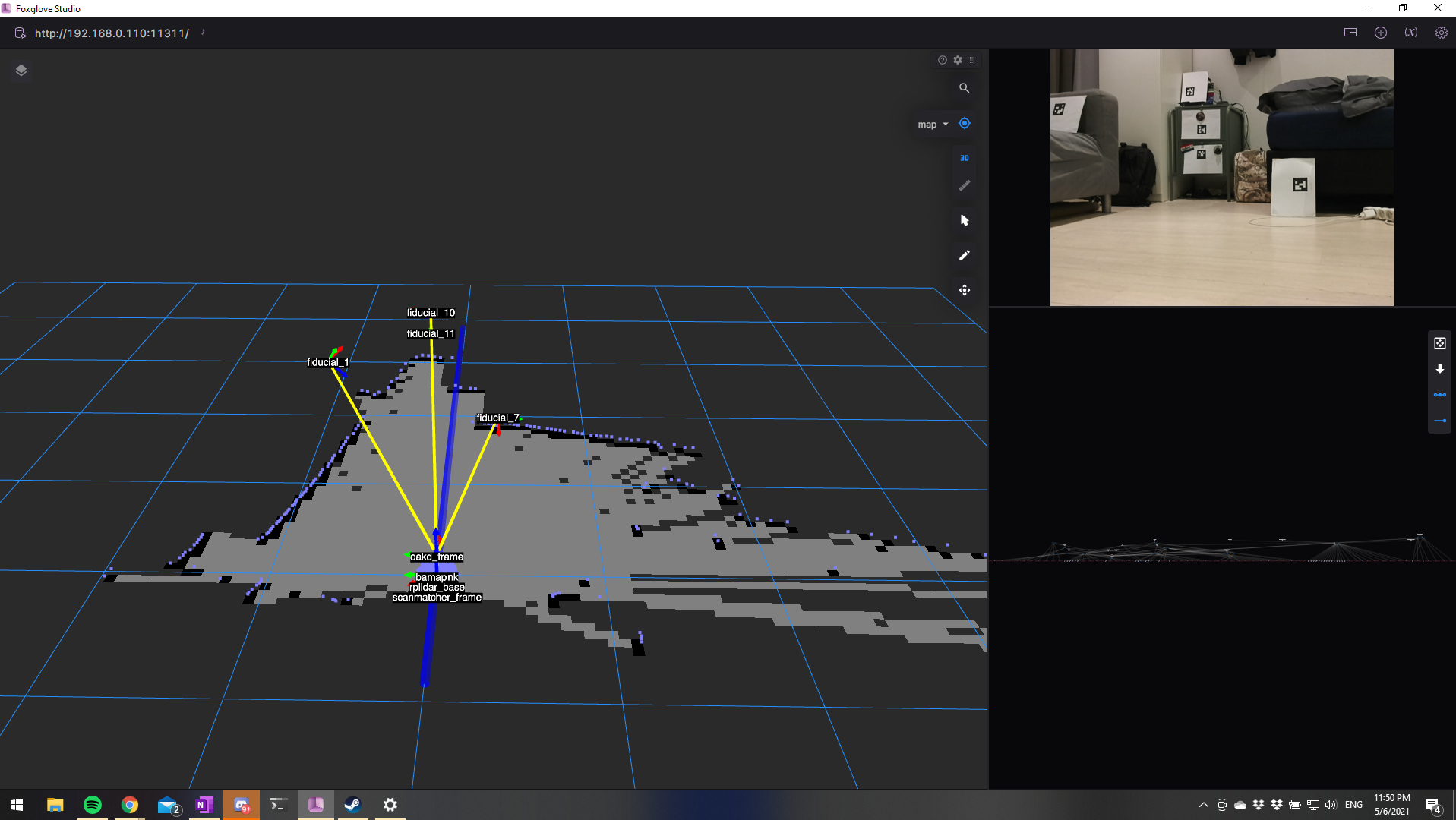
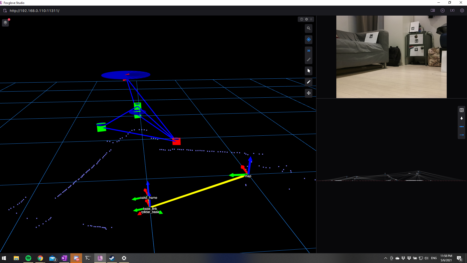
This week, I accomplished quite a few things. First, I installed a dev tool called Foxglove on my Windows laptop. This tool is essentially Rviz (+ some additional features) for Windows and connects remotely to a ROS machine. This saved me a lot of time, since I dont need to setup a ROS machine on my windows PC and start Rviz from there, but not all features always work. Foxglove doesn’t have all the features of Rviz just yet, but since its an open source project, I hope to see some new developments in the near future. For the time being, I can still work with it. Here’s the Hector SLAM example being visualized using Foxglove:
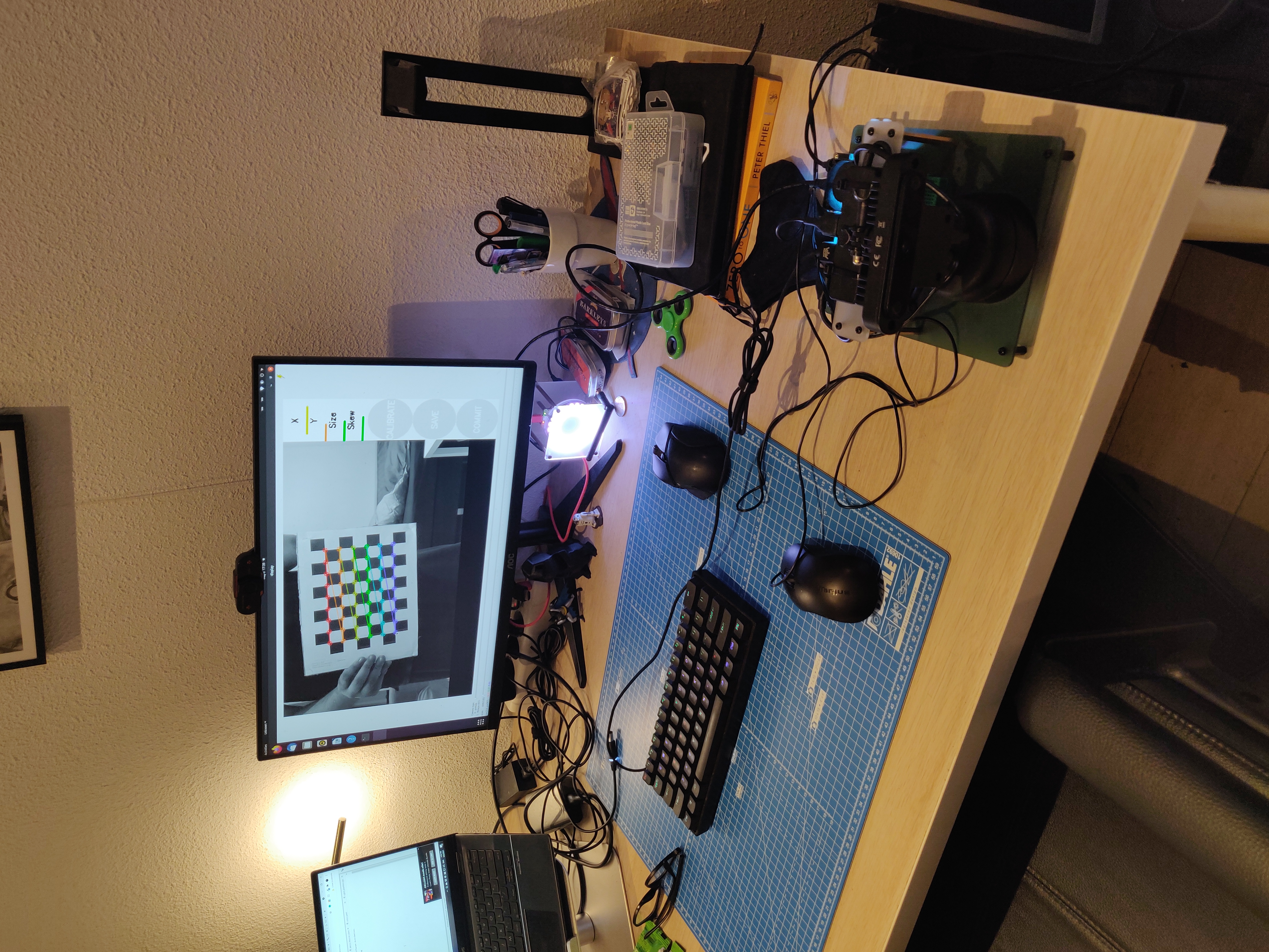
Next, I printed some Aruco markers and used the aruco_detect node from this ROS package by Ubiquity Robotics to detect the Aruco markers that I placed around my studio. This is when I realized that the aruco markers were not being detected in the exact location they were actually in. On debugging, I realized that the OAK-D camera is originally calibrated using a 480p image. Since I was using a 720p image, I had to calibrate the camera using the correct images, and I did that using the camera_calibration node from the image_pipeline package. I needed a checkerboard and the camera_calibration node provided a handy GUI, so I had the camera calibrated in no time.
Once calibrated, the aruco markers were being detected in the correct location.
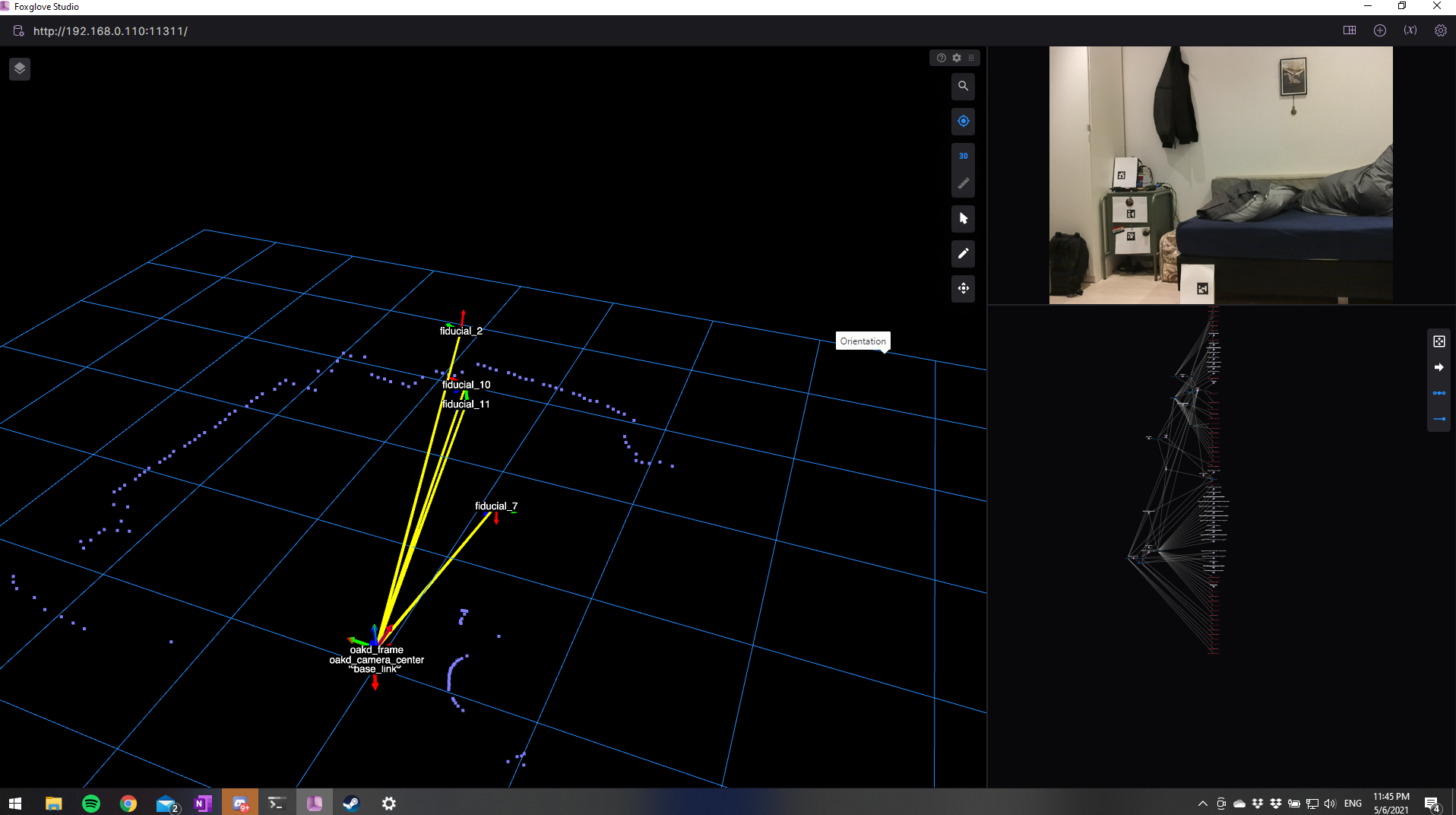
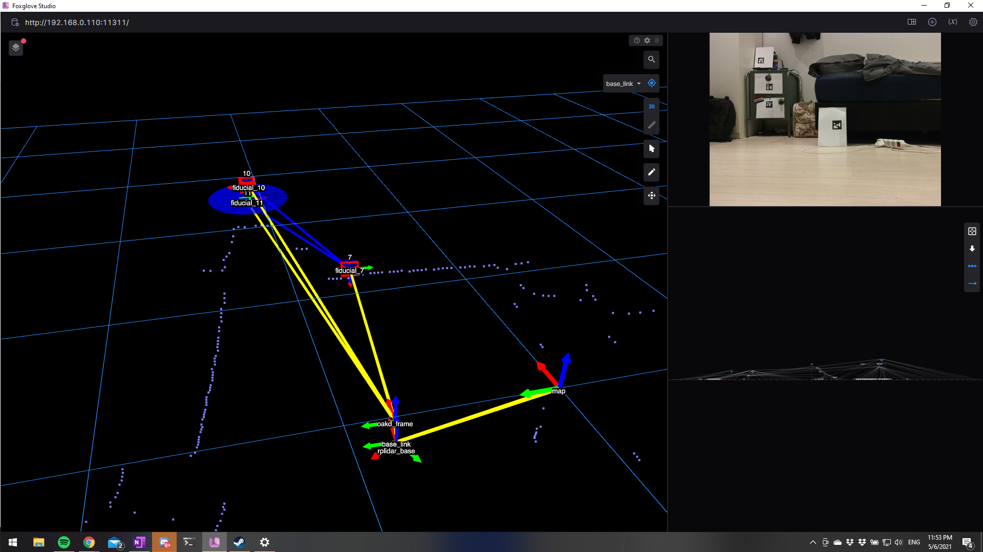
Finally, from the same package of Ubiquity Robotics, I used the fiducial_slam node and configured to work with the aruco detections. This package uses these detections to create a map, which it then uses to localize. Here are images of the robot mapping and localizing:
For the next few weeks, I want to work with the mobilenet detection and spatial detection nodes from the depthai_ros_examples package by Luxonis. I want to accomplish two things: first, to publish transforms for each detection, and second to publish a preview image with the bounding boxes drawn. But first, I want to make a nice demo video of what I’ve done so far. Meanwhile, I am also doing some ROS2 tutorials and hope to start making some small ROS2 projects soon. I also recently purchased some ESP-32 boards for side-projects and ever since I read about microROS on an ESP-32 DevKit-C, I have been dying to try them out with some ROS2 robots.
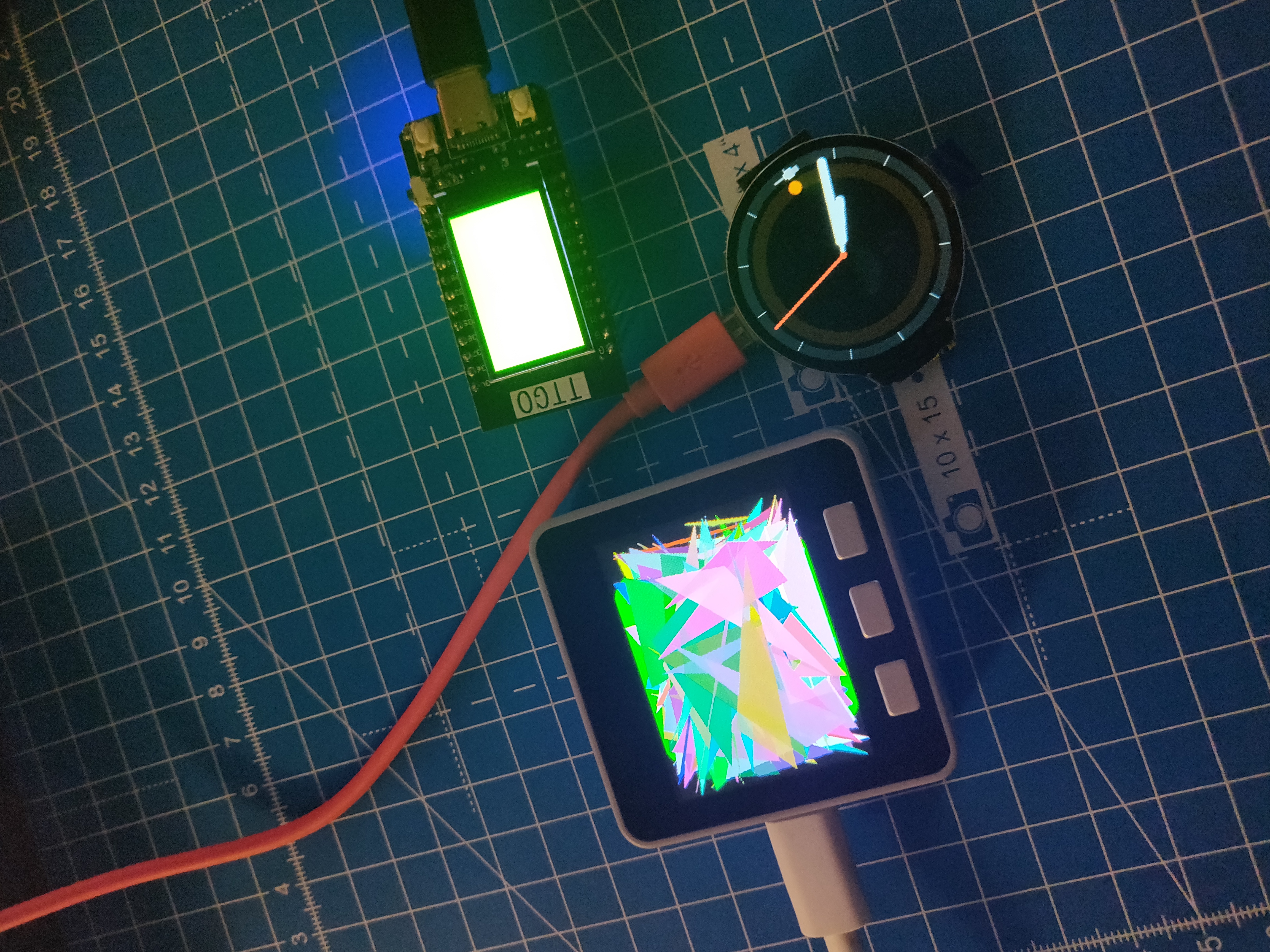
M5Stack Core Grey, Open-SmarWatch and a TT-Go. I also have an ESP-32 DevKit-C as well, but not in the picture.
I had originally planned to implement RTABMap in the next few months, but looks like this will take a while. I’m still waiting for support from Luxonis about publishing disparity instead of depth, and about depth-RGB alignment. Hopefully by the time I’m done learning about ROS2, microROS, they have some updates and I can implement RTABMap. I’ll also probably upgrade to a RPi4 8GB or a Jetson device by then, for better performance.