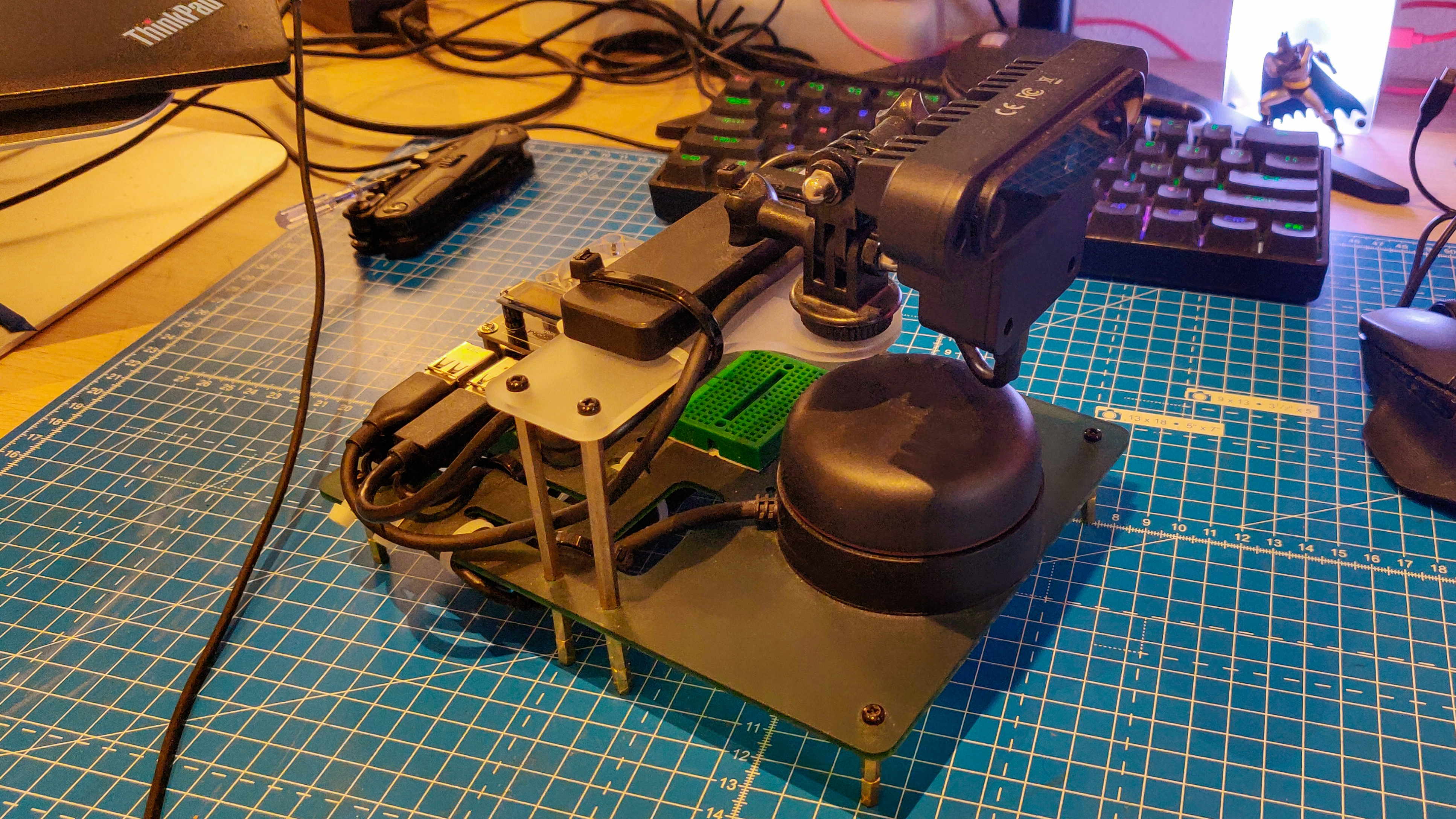
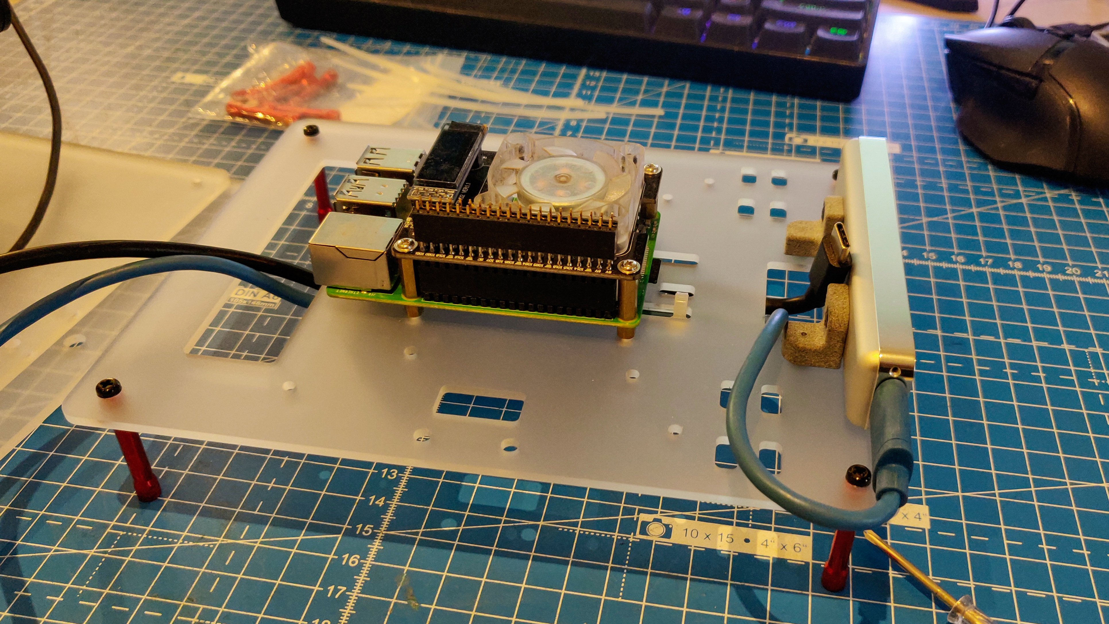
This week, I finally attached my new Intel Realsense T265 tracking camera to my robot platform. Of course, I need to make space for this, so I naturally redesigned the entire frame. Fortunately, this also gave me the opportunity to fix some of my earlier errors. The previous platform, looks something like this:
The old platform without the Intel T265 tracking camera
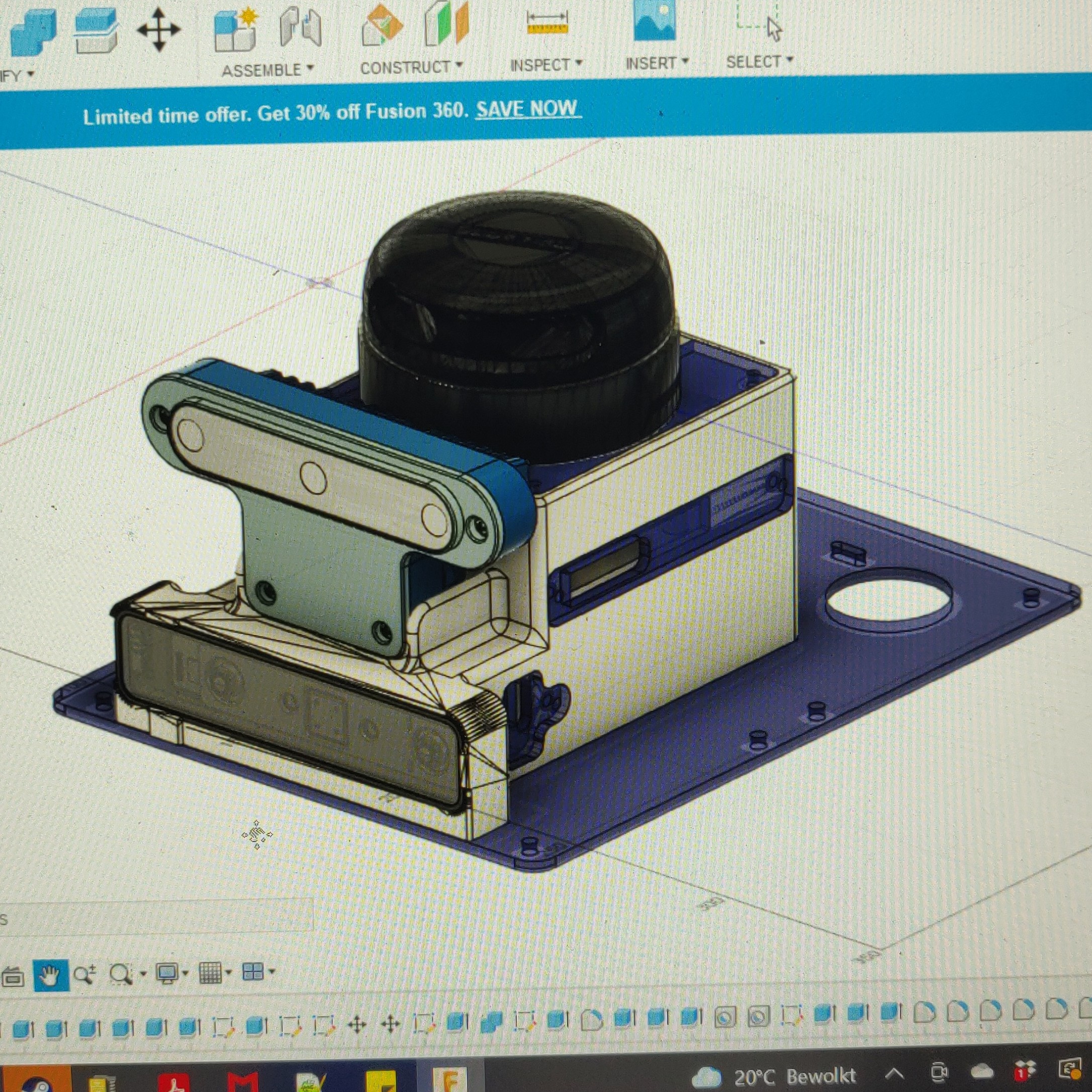
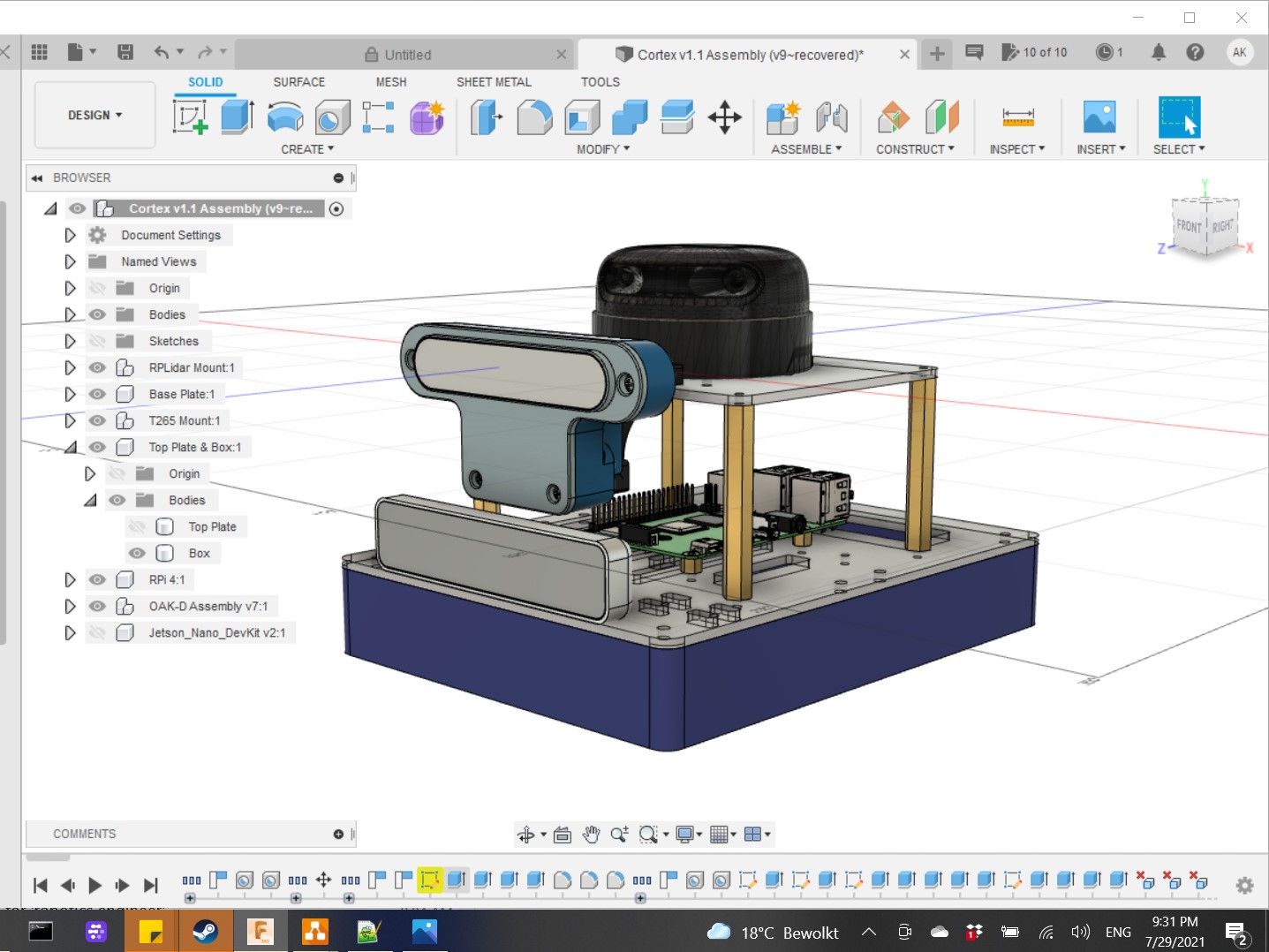
The first mistake I made here was the position of the lidar. It needed to be on the top to be able to cover 360 degrees. The second mistake was the flimsy design of the top plate where the OAK-D is attached. Because of the weight of this attachment, the top plate bent by about 10 degrees and I feared it would bend even more and hit the lidar. In the new design, I wanted the lidar on the top, without any obstructions. The OAK-D also had to be elevated from any base plate, because of the weird position of the cable input ports. Finally, I had to make space for the Intel Realsense t265 camera. Optionally, I also needed mounting holes for a Jetson Nano in case I ever decided to switch back to it from the RPi4. After multiple iterations (each having some really complicated 3D printed parts, which would take hours to print), I finally landed on this combination of laser cut acrylic parts and minimal 3D printed mounts. This is the finaly 3D model:
First iteration of the design. The single 3D printed part would have taken approximately 18 hours of print time.Second and final iteration of the design. Minimal 3D printed parts and more laser-cut acylic. This now takes less than 3 hours to make. The bottom box is currently replaced by another plate and spacers, but I plan on getting it CNCed in wood (good chance for me to learn how to use the CNC machine)
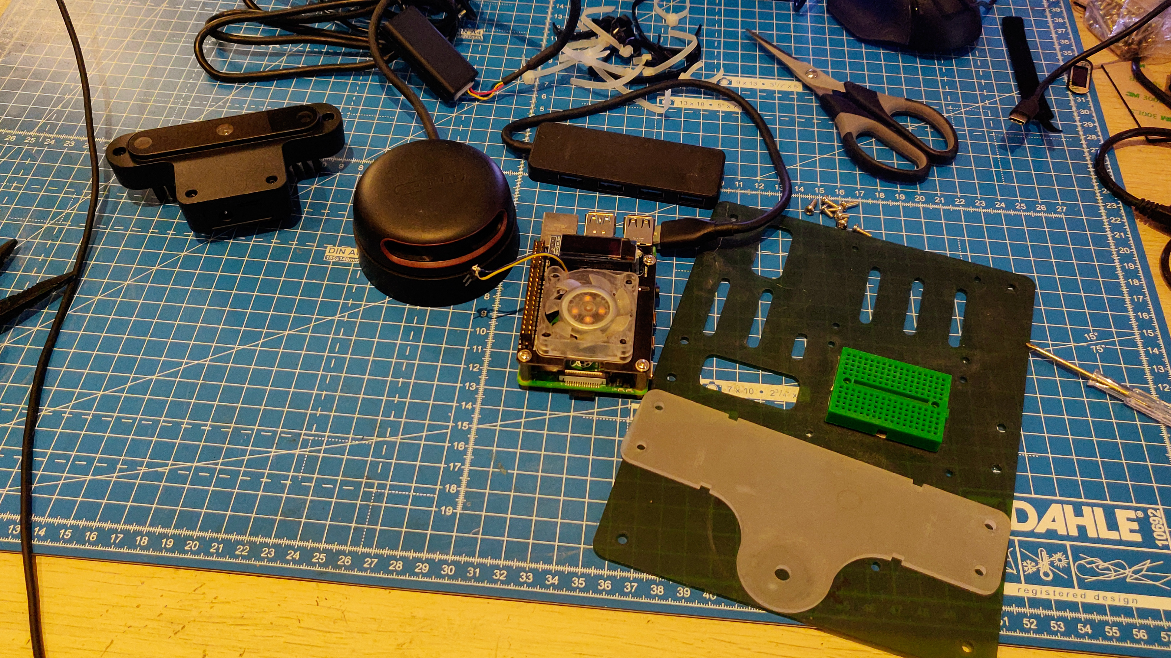
The next step was to get these parts 3D printed, laser cut, and finally, assembled. While I waited for these laser cut parts to arrive, I also decided to outsource some of the work and hired a freelancer to use the CAD model and build a URDF file for me. The following pictures show the assembly process:
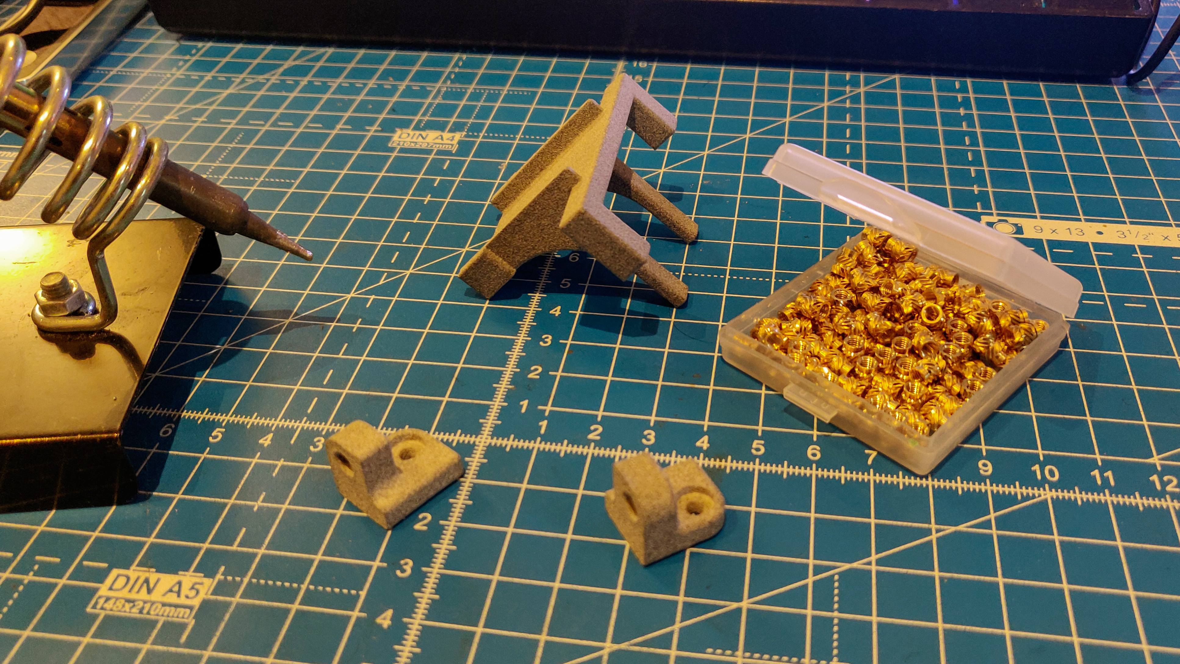
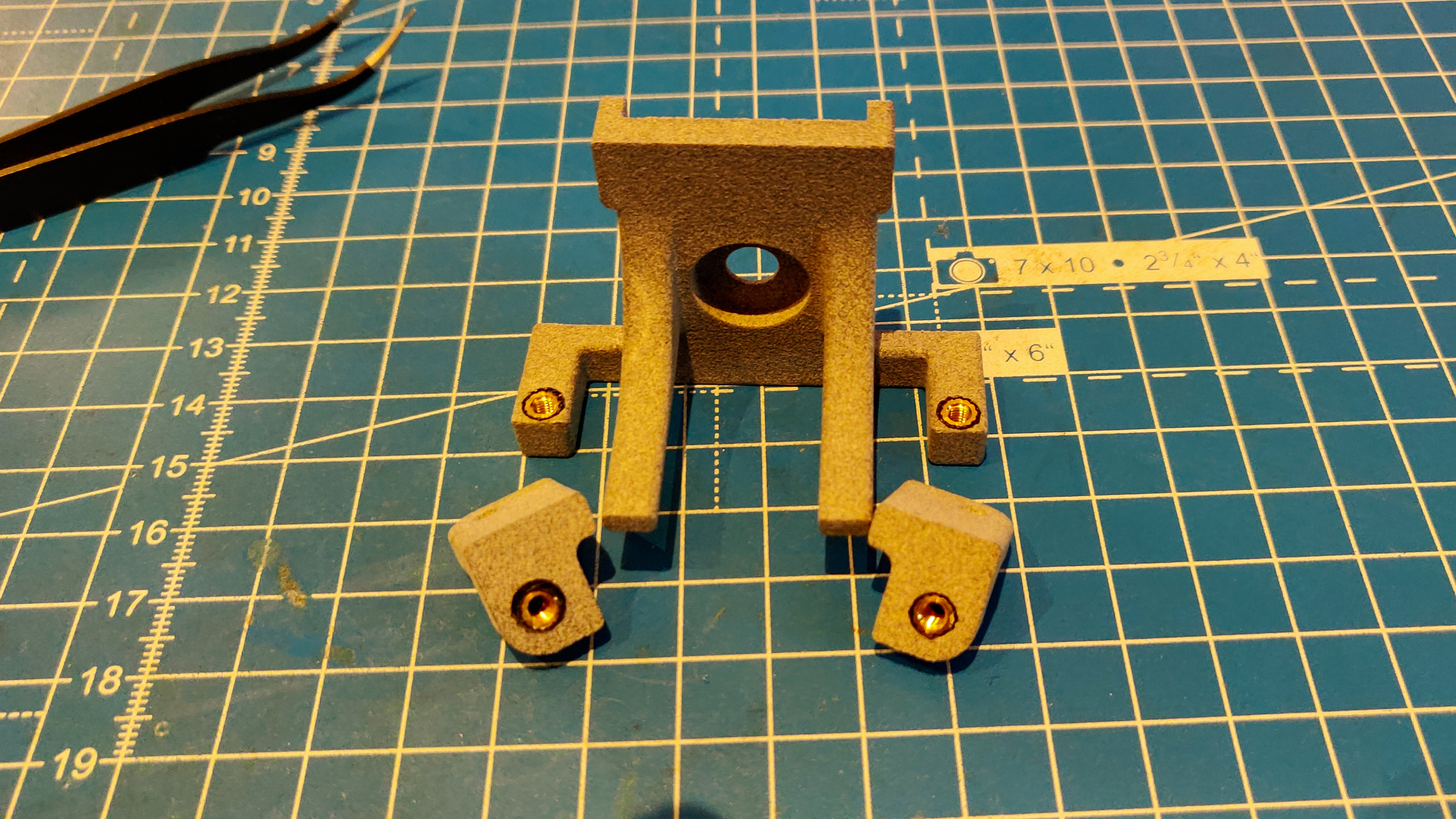
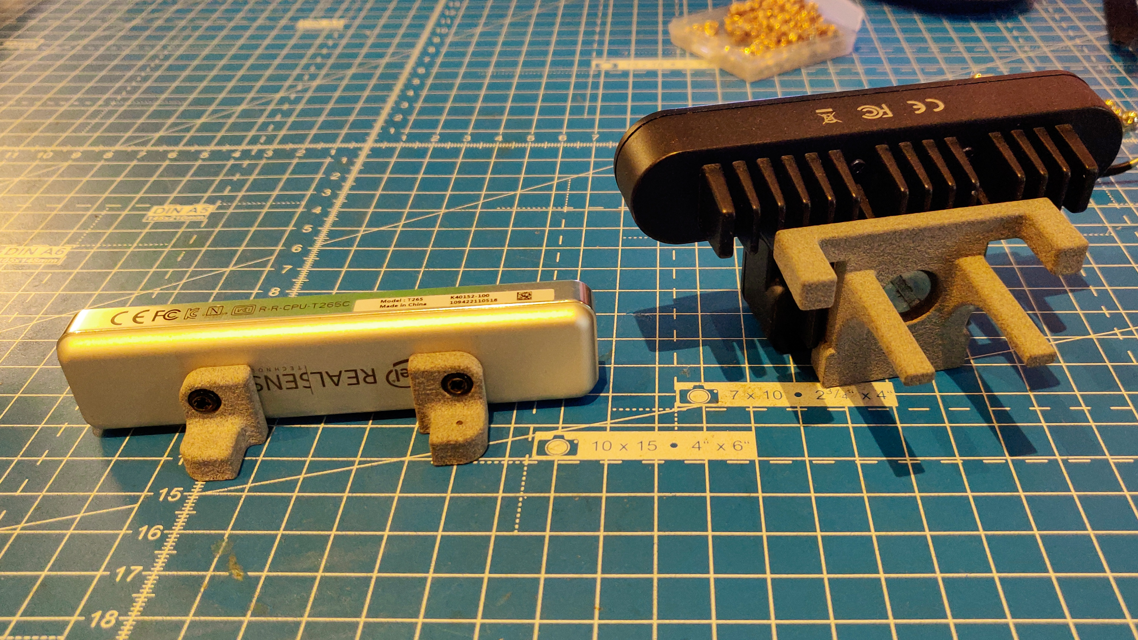
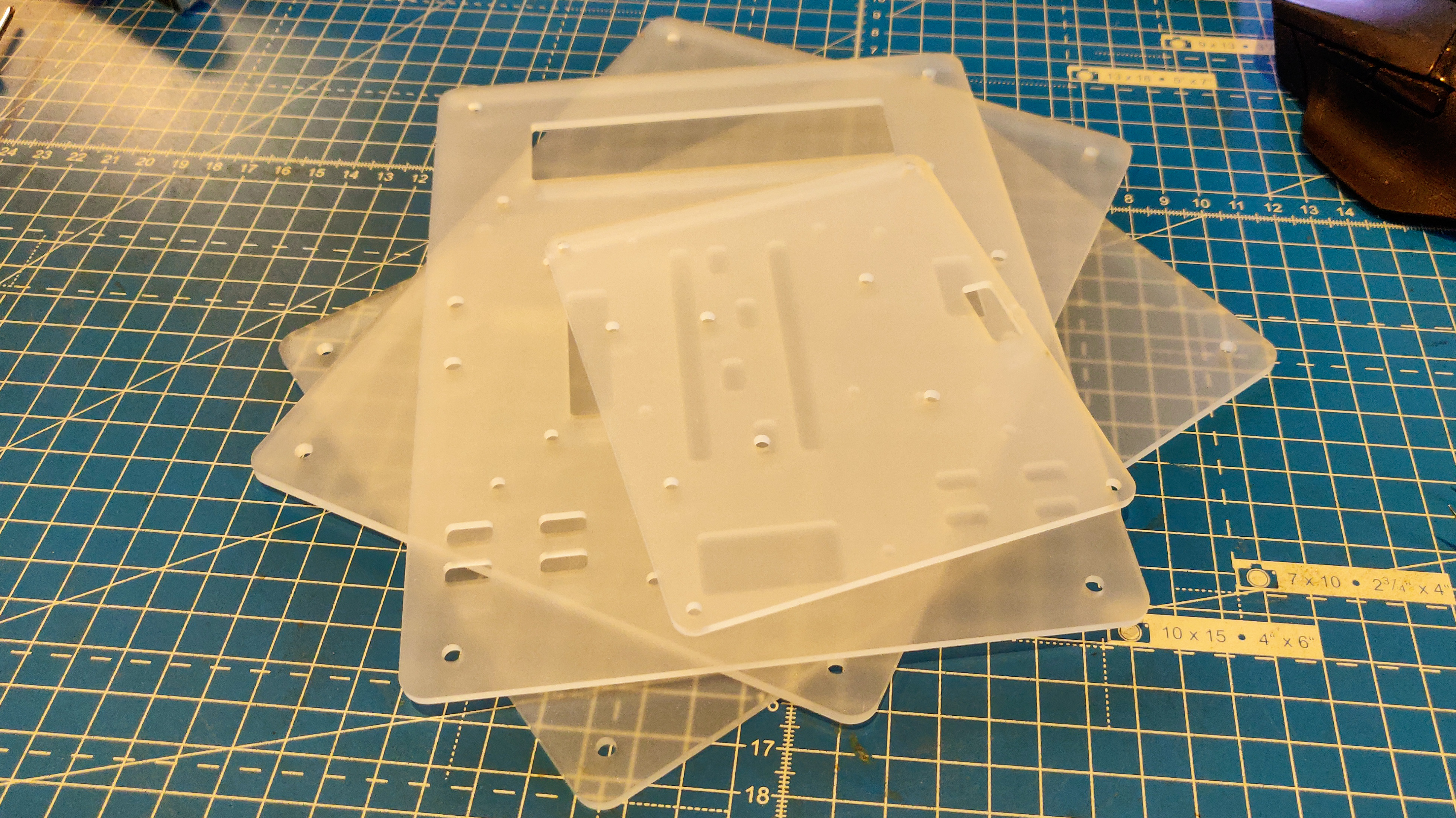
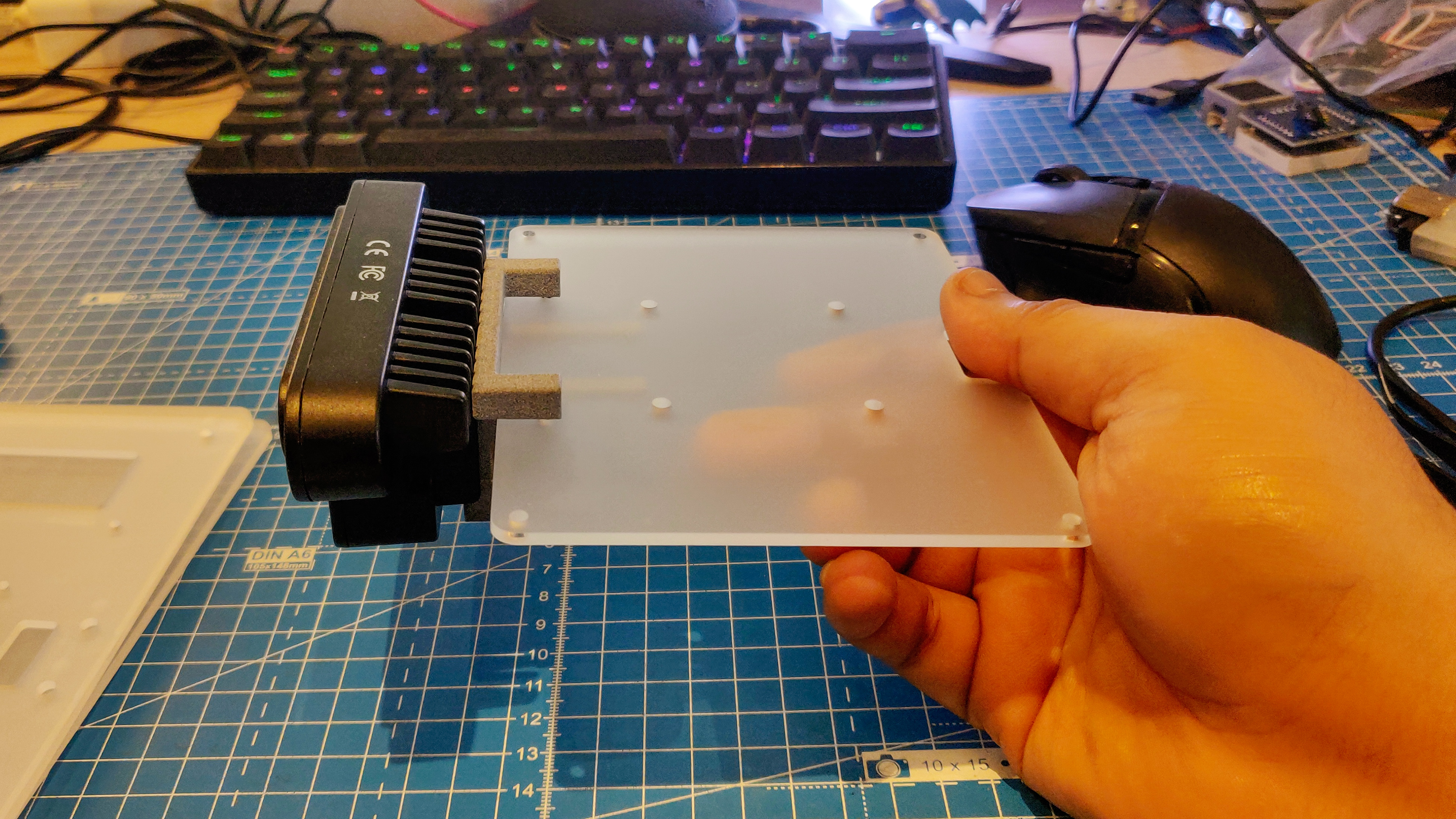
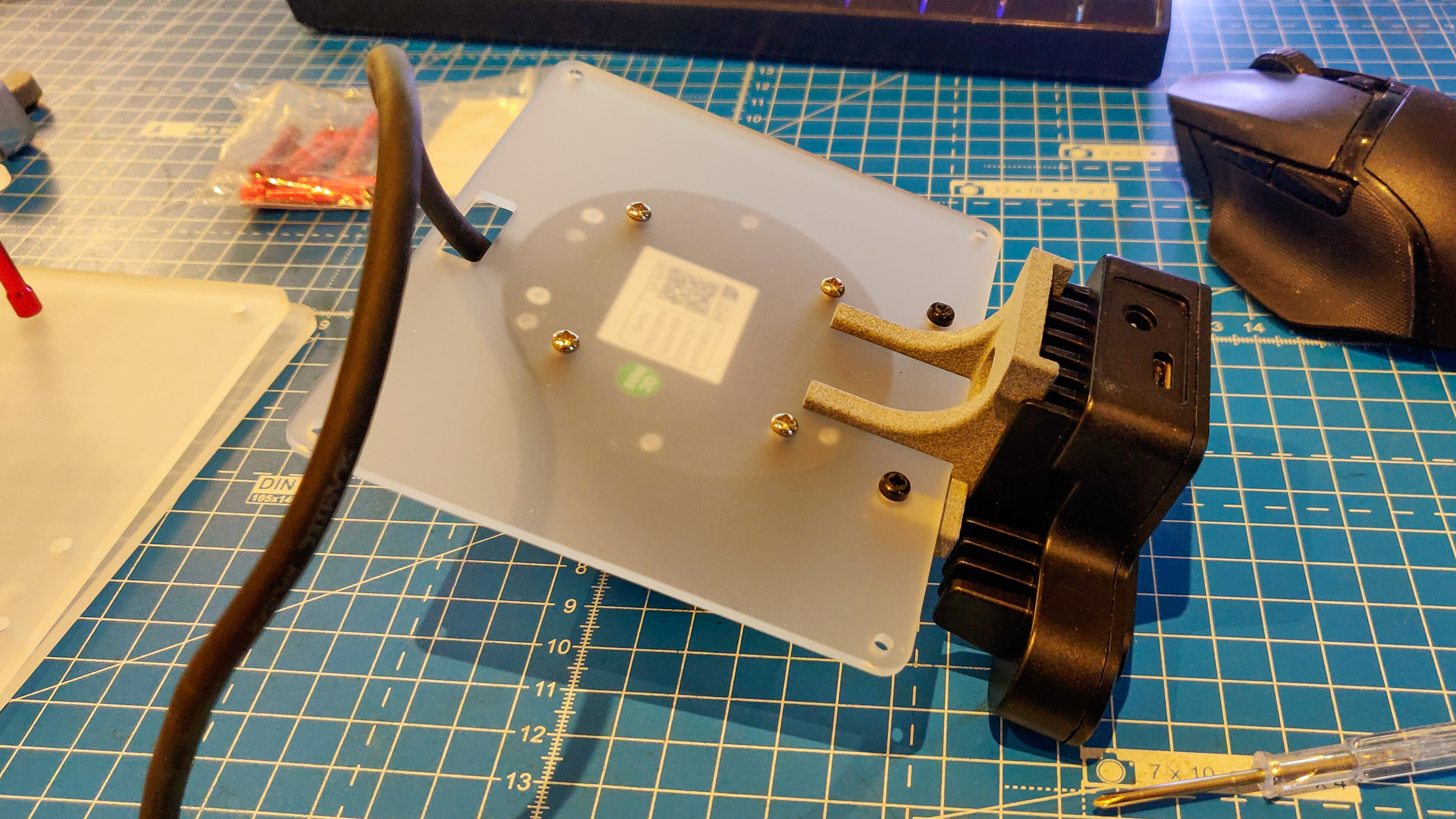
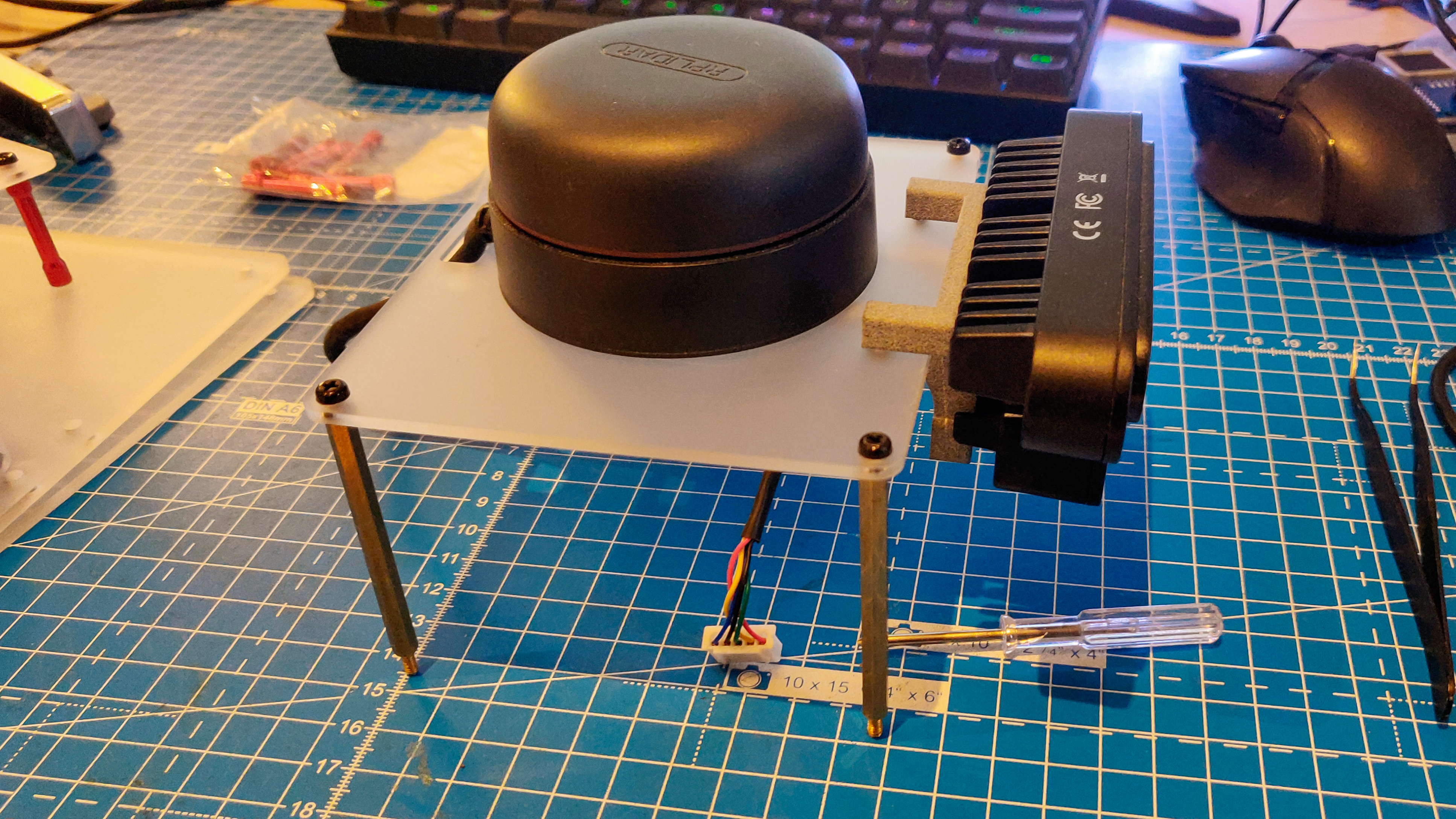
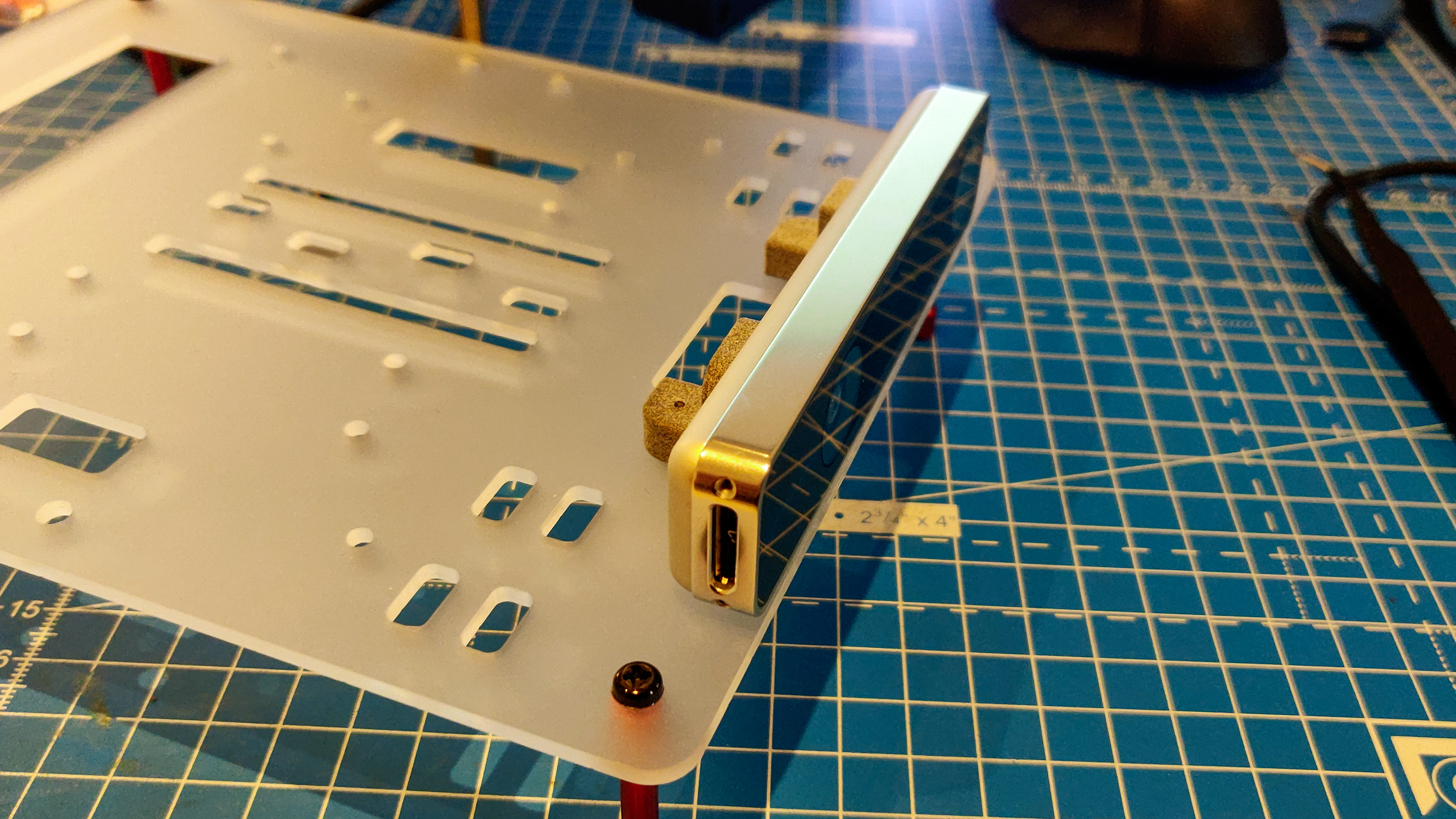
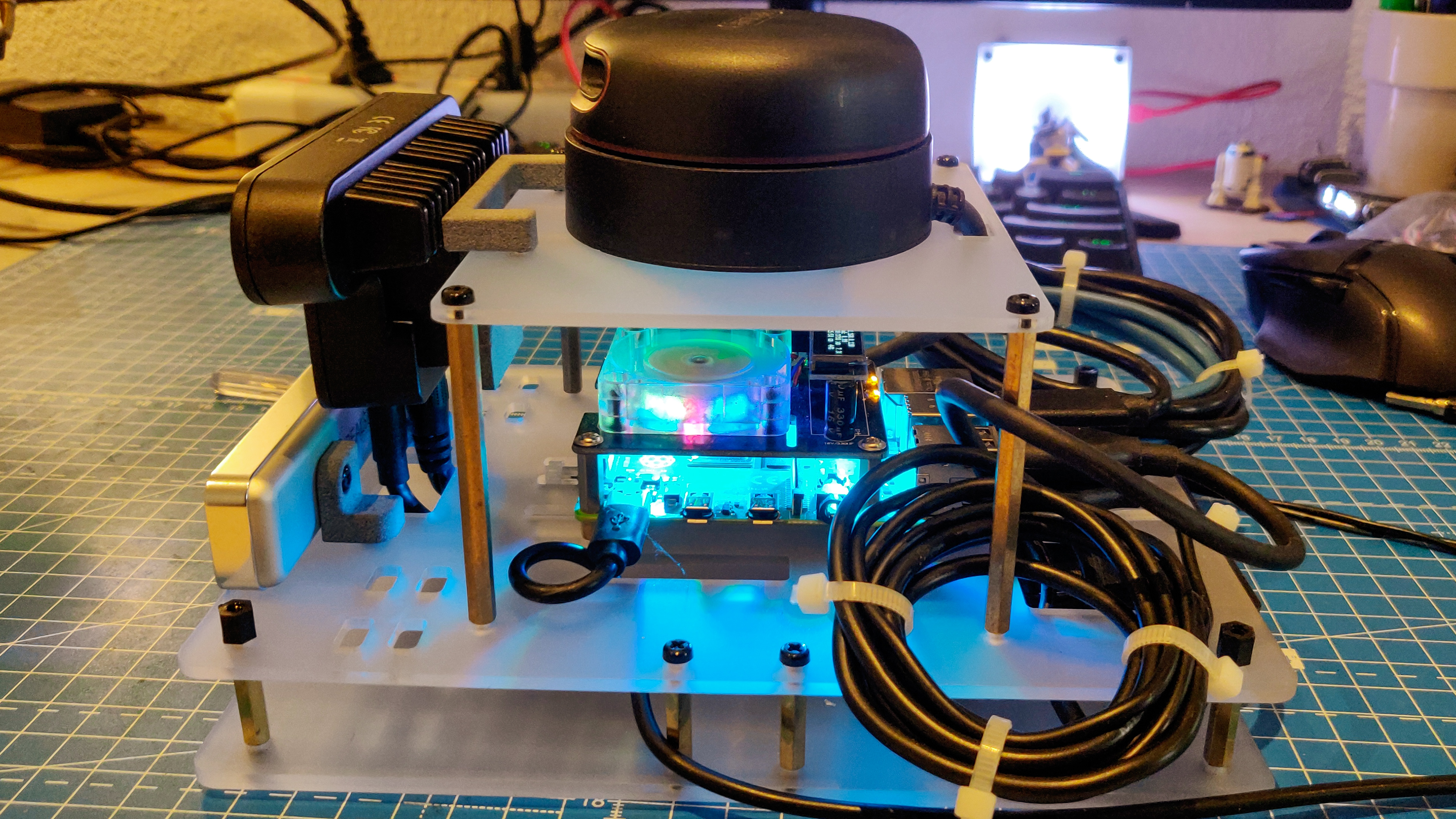
First step: disassembly. The OAK-D, the RPLidar and the RPi4 move on to the new platform. The two smaller mounts are for the T265, the bigger mount is for the OAK-D, to be mounted on the RPLidar base plate. This was the first time I designed anything with threaded inserts..Threaded inserts are very cool! This is how the parts look after the inserts were (almost) successfully added.The T265 camera (left) and the OAK-D (right) attached to their mounts.The acrylic parts for the build from Snijlab.nl. I really like this translucent acrylic, you'll see why in the coming pictures.Its always a great feeling when parts fit together perfectly. Unfortunately, this was not the case for me. I had accounted for a 3mm clearance, but the acrylic part was almost 2.5mm, so the fit was quite loose. Luckily, I had a way of attaching screws and fixing it.the OAK-D mount and the RPLidar and firmly attached using M3 nuts from the bottom of the plate.The plate can now be turned the right side up and elevated using 6cm brass M3 spacers. This elevation is enough for the RPLidar to be on top of all other sensors, and also for the OAK-D to be at a sufficient height so as to allow cables to be inserted from below.The t265 mount is attached using M3 nuts from the bottom of the base plate.The RPi4 can then be attached to the base plate. The RPi4 has the same RGB fan hat as before, which is a really colorful addition. As seen in later pictures, it makes the acrylic really glow. As shown, the base plate is held up by spacers (instead of the bottom box). This space allows for cables to be managed in a neat way.This is how the assembly looked once all wired up. The wires were tied up at the side for testing.This is how the platform looks like after all wires were pushed underneath the base plate and zip-tied neatly. I made sure to click the picture from the same angle as the CAD screenshot..
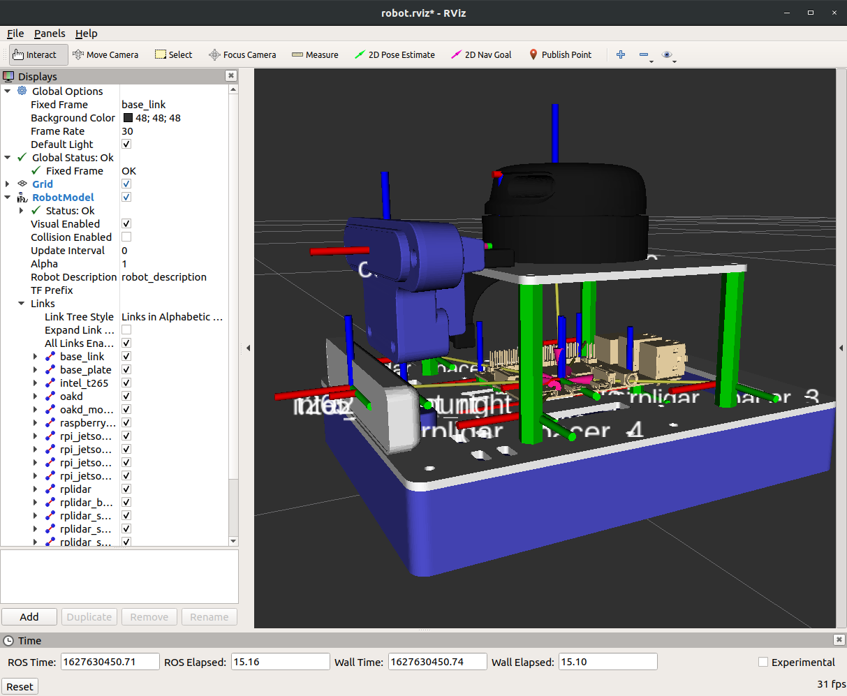
By the time I had this robot assembled, I had heard back from the freelancer on Fiverr and the URDF file was ready! This is what it looks like:
URDF file made by the freelancer on Fiverr.com. Looks good but the frame references for the sensor outputs are not aligned correctly. See the axis on the Lidar for example..
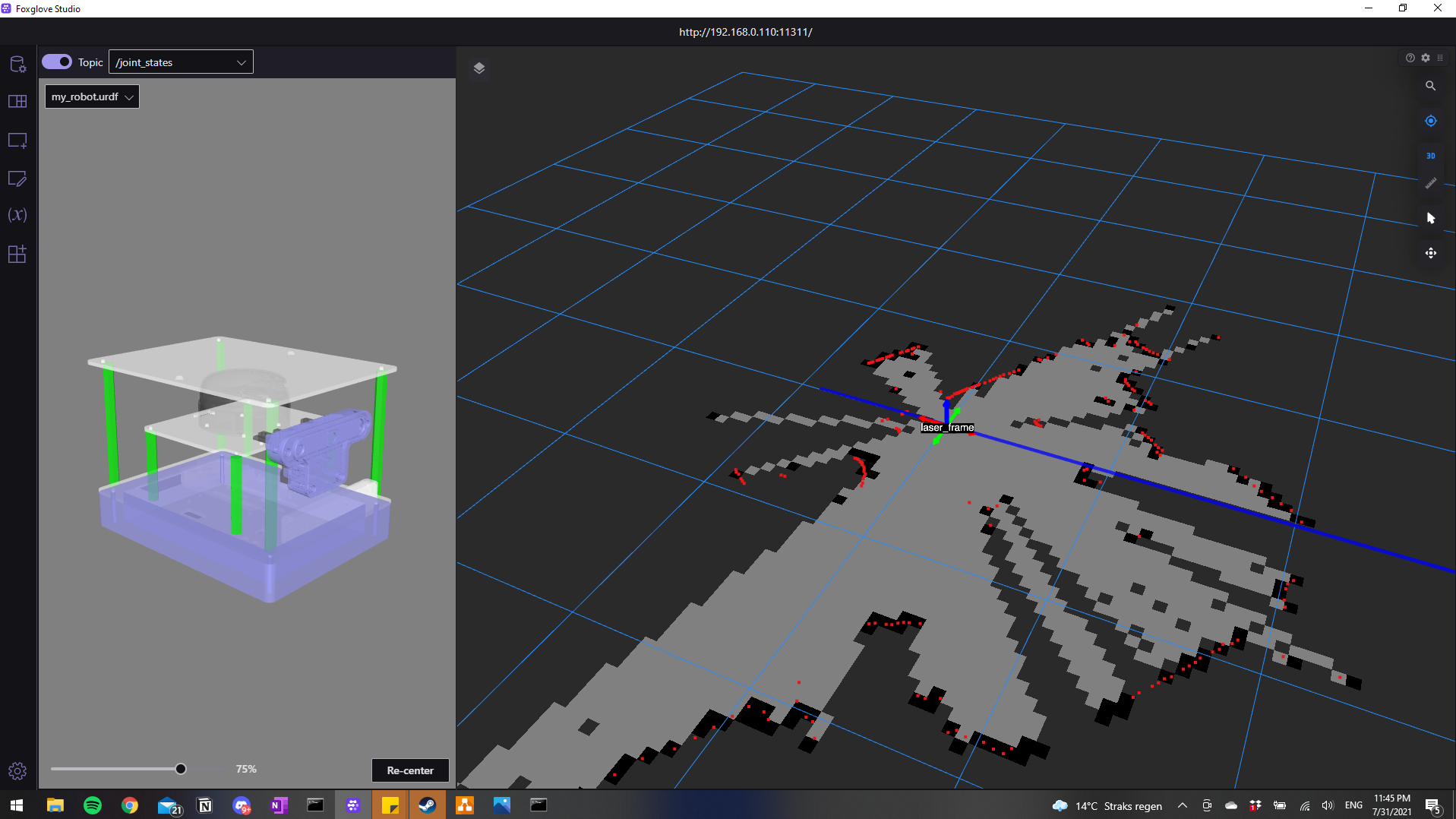
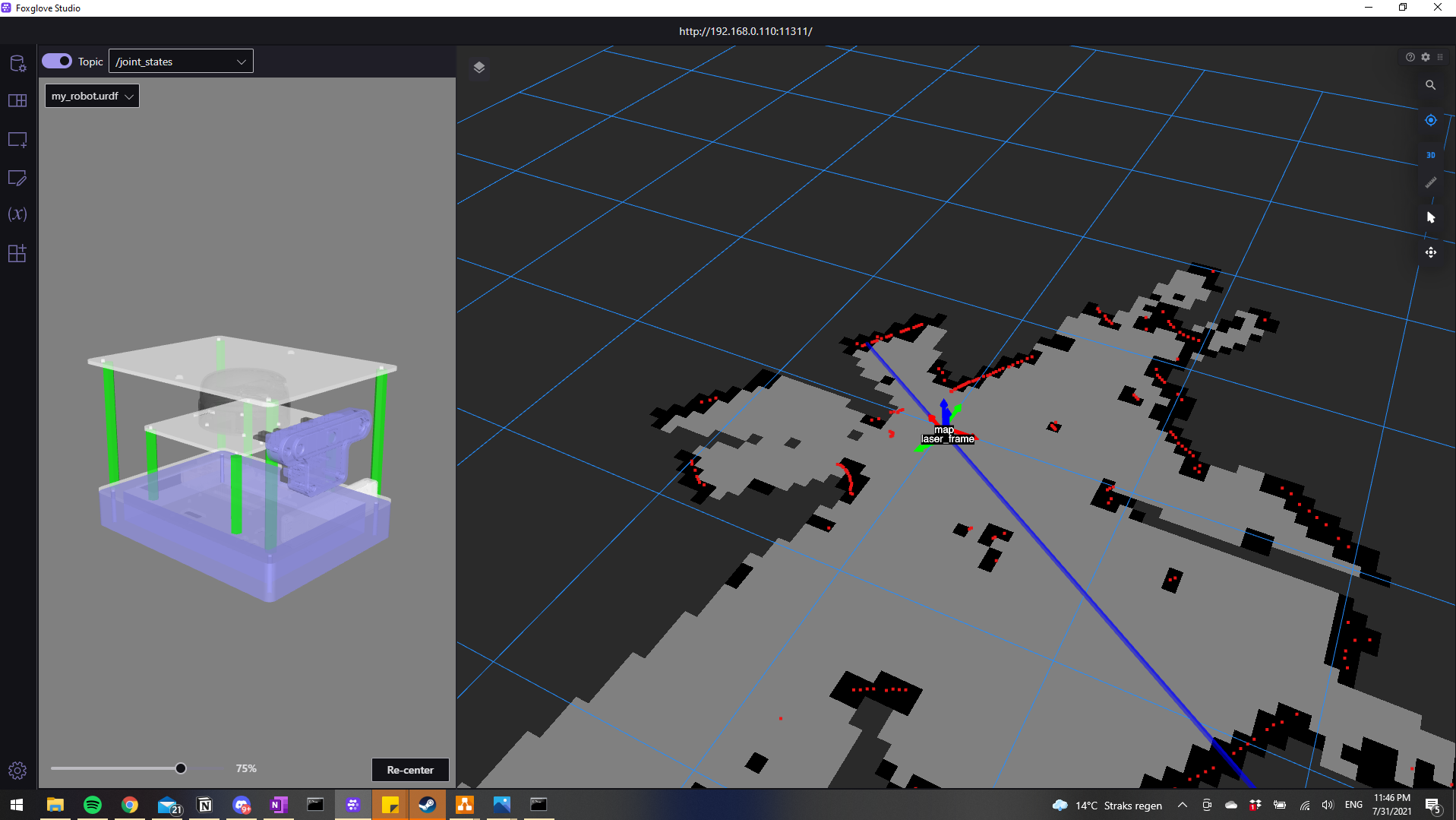
I was pretty impressed! It didn’t cost me a lot of money either, so now I can at least pay for some help if I cannot find a collaborator!! Jokes aside, the work was not entirely complete. While the URDF file was as per my CAD model, the freelancer wasn’t accurate in defining the frame references for each of the sensor output streams. So, while the job didn’t cost a lot, I do have quite some rework that I need to do myself. Meanwhile, I used the slightly off frame references provided by the freelancer and did manage to get a basic hector_slam and gmapping running with the RPLidar providing the laser scan and the T265 providing odometry data. The sensor seems to work perfectly and while Intel recommends that T265 should be used with encoder odometry for wheeled robots, it works quite fine without any additional inputs. I’m super impressed. Here are some pictures:
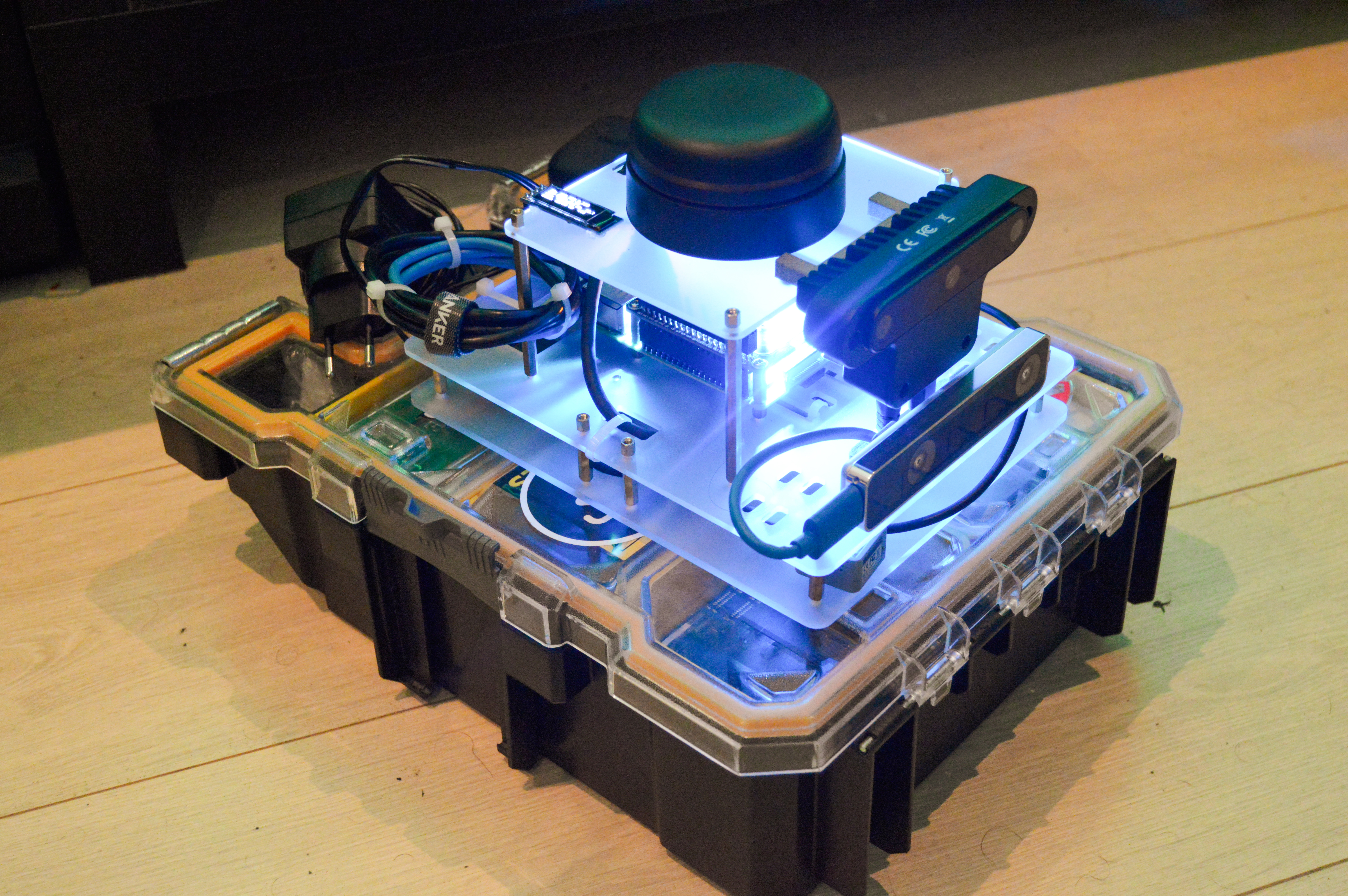
The navigation module so far only represents the top part of the robot, and the bottom part is currently with a friend. However, I found out that my electronics container box is the same height as my robot base, so just placing the navigation module on top helps me demo SLAM applications by just moving the box around with my foot. And since the height is the same, I expect the same performance when I put it on top of the actual robot base.Visualization of the map created using a basic implementation of Hector SLAM. Visualized on Foxglove StudioVisualization of the map created using a basic GMapping implementation
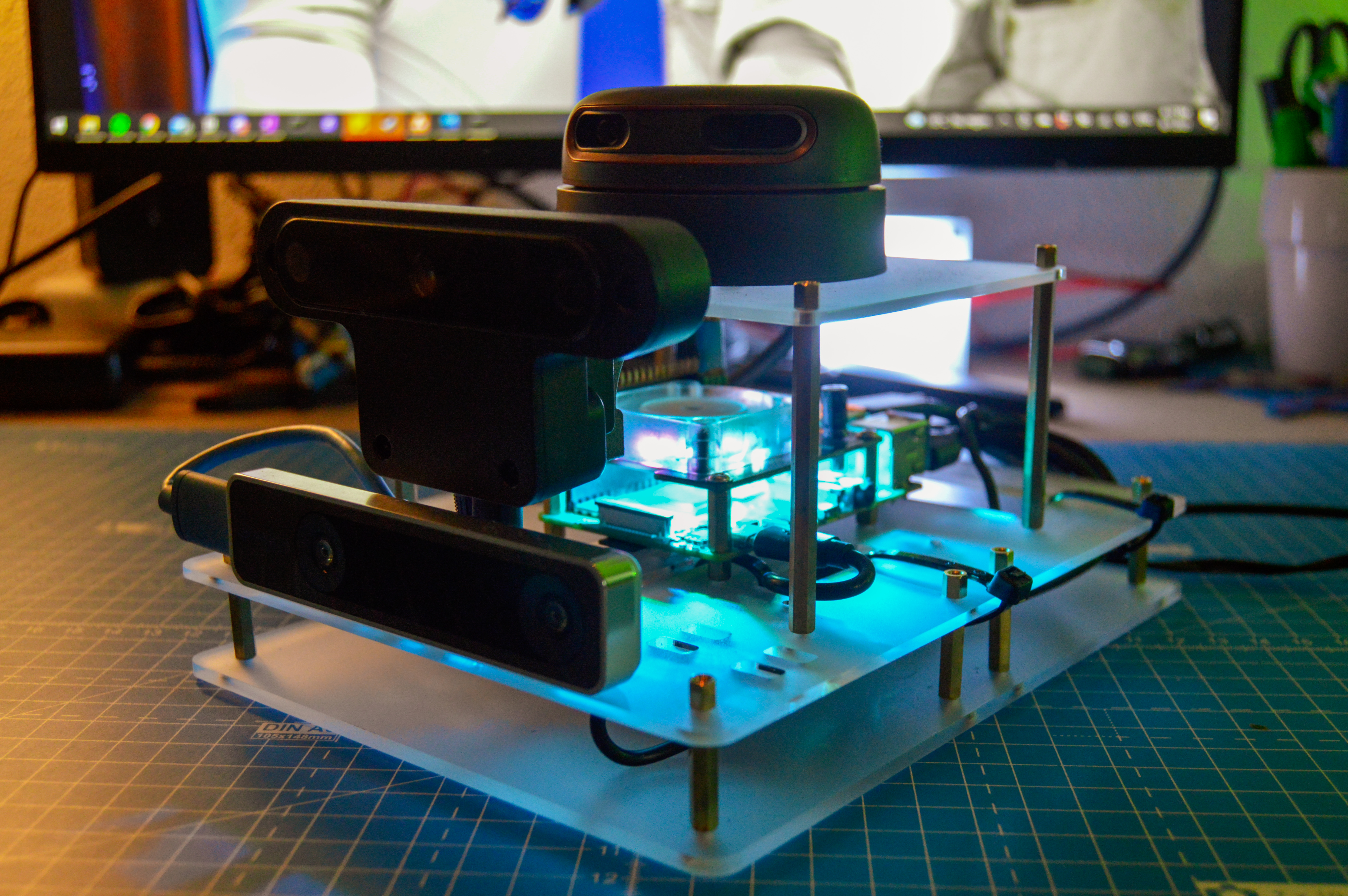
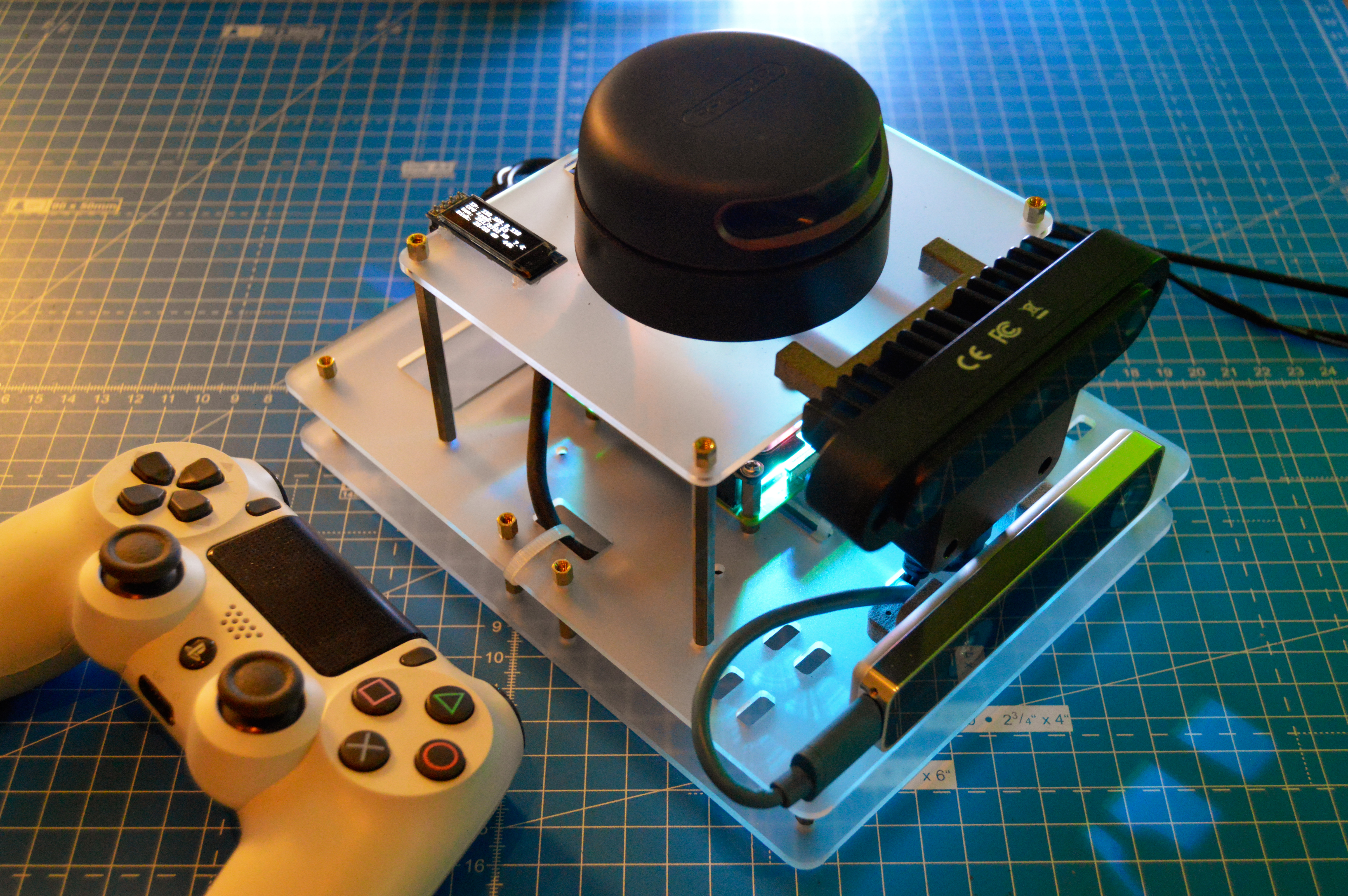
My next steps are to fix the URDF (I am getting vaccinated this week, and also need some well deserved time off, so I’ll probably hire someone else on fiverr for this) and then setup the ROS navigation stack. Once this basic configuration is working, I can then setup the drive system and move_base. More updates next weekend, meanwhile here is a final picture of the navigation module in all its glory..
The navigation module looking perfect! I really love how the acrylic glows because of the LED fan underneath. Also seen is a PS4 controller that I plan on using to move the robot around for mapping.