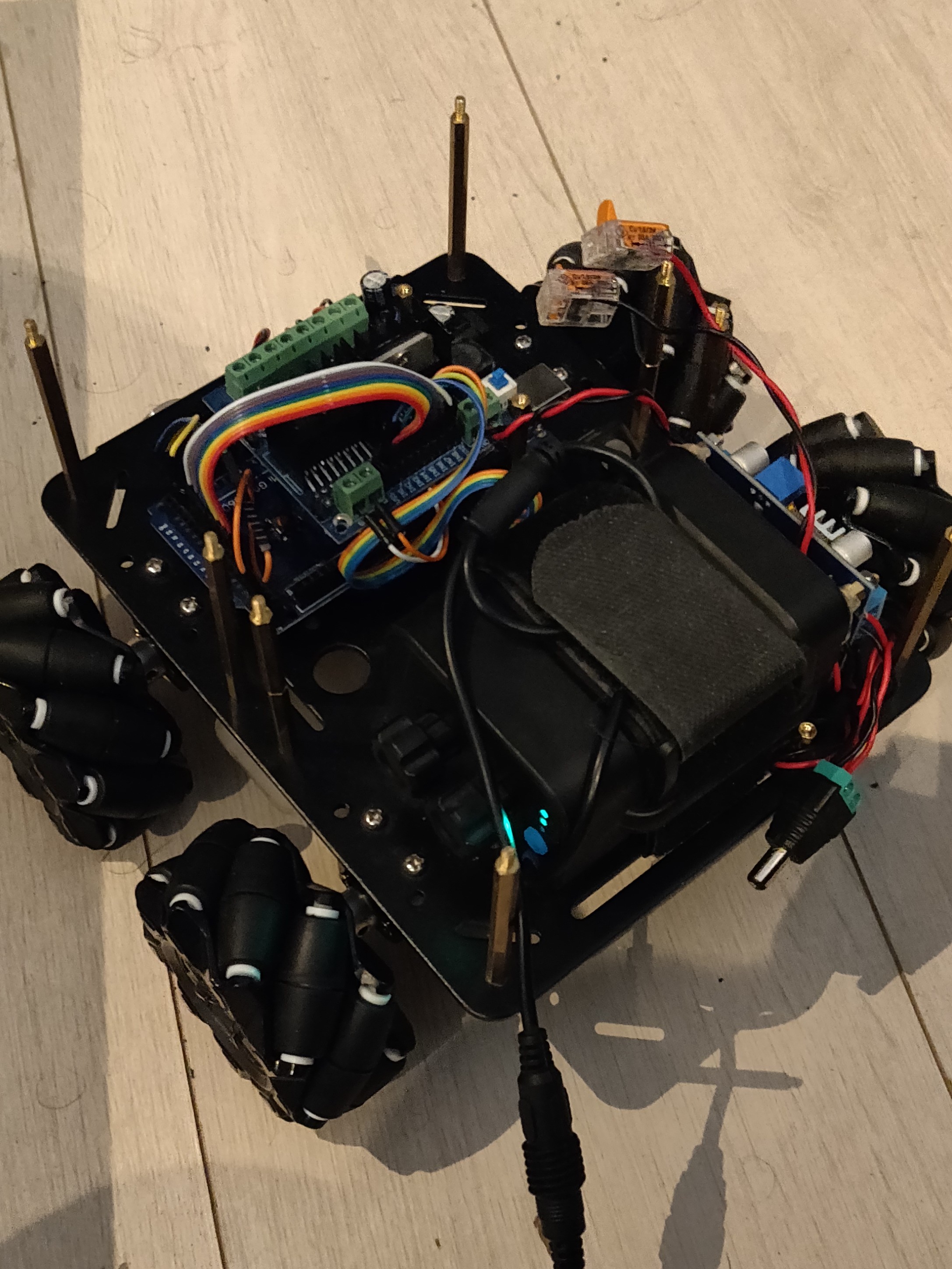
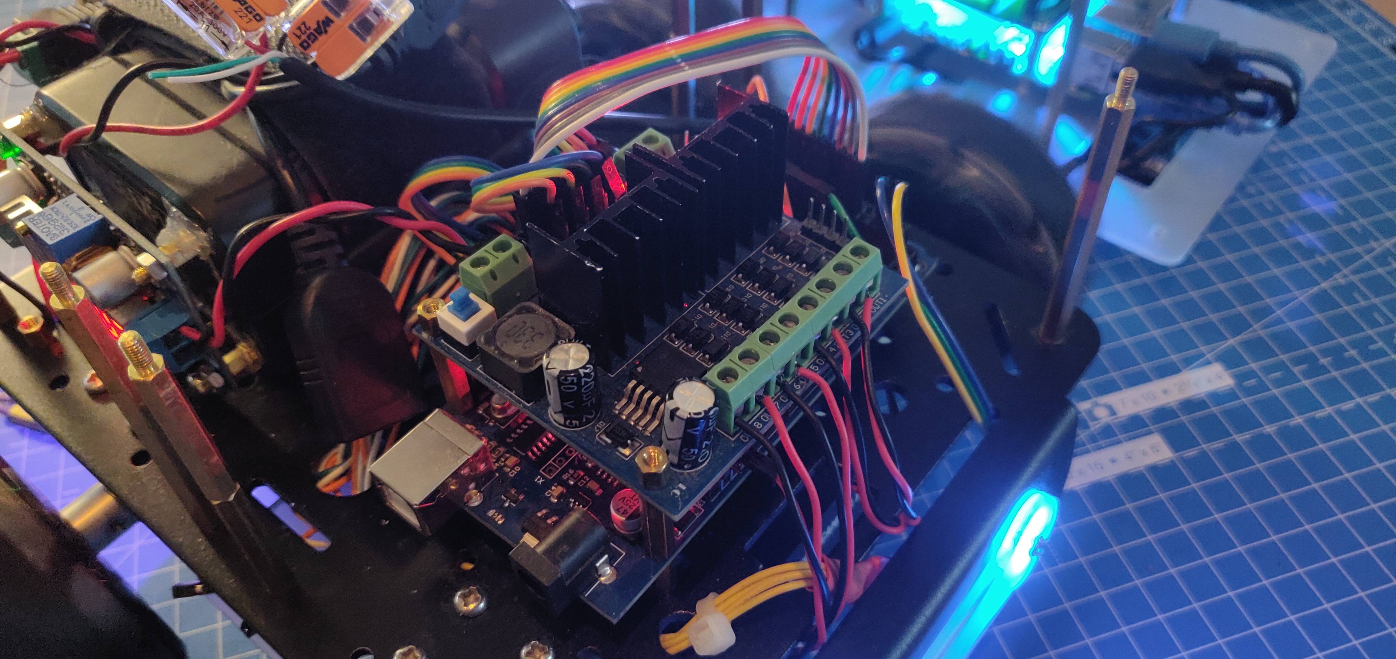
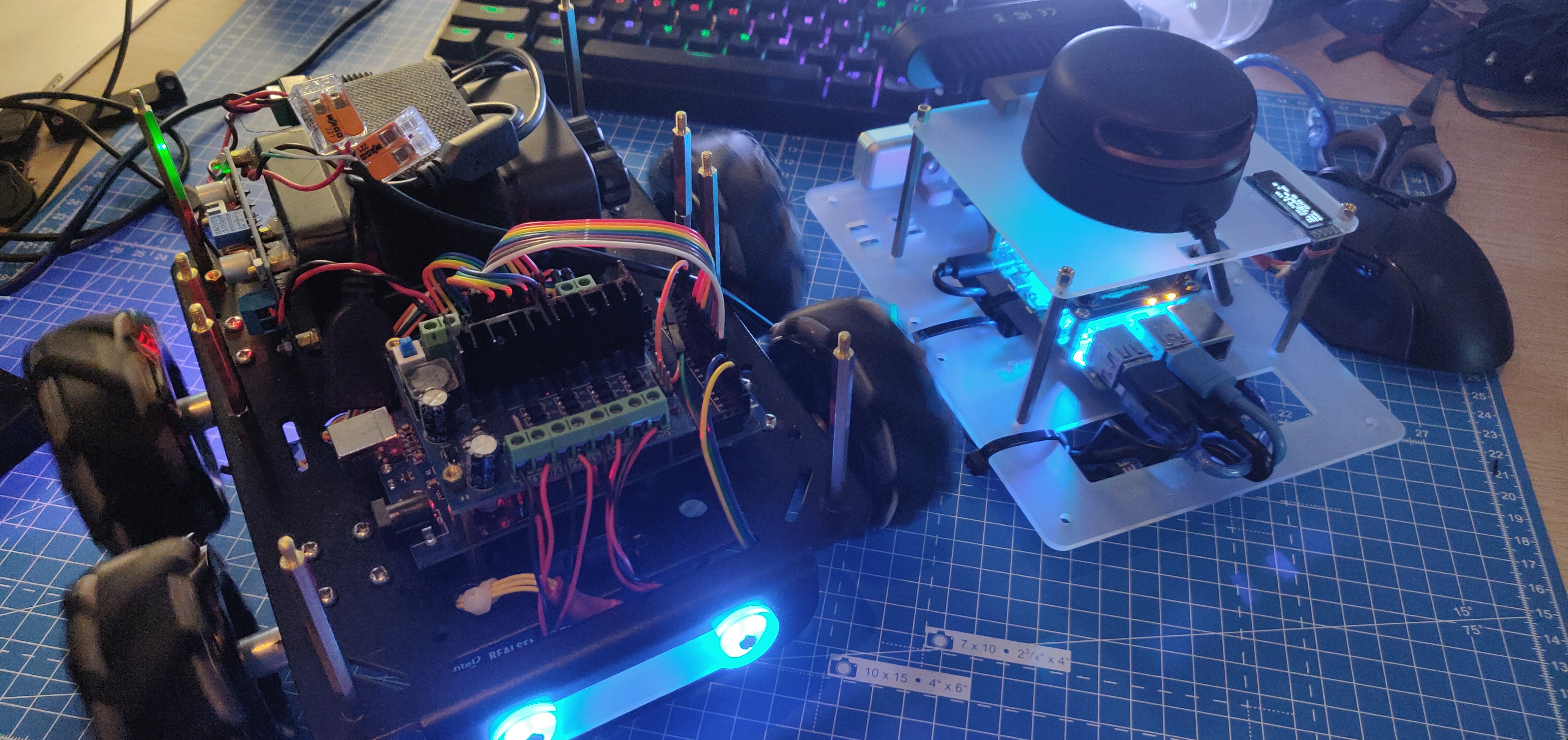
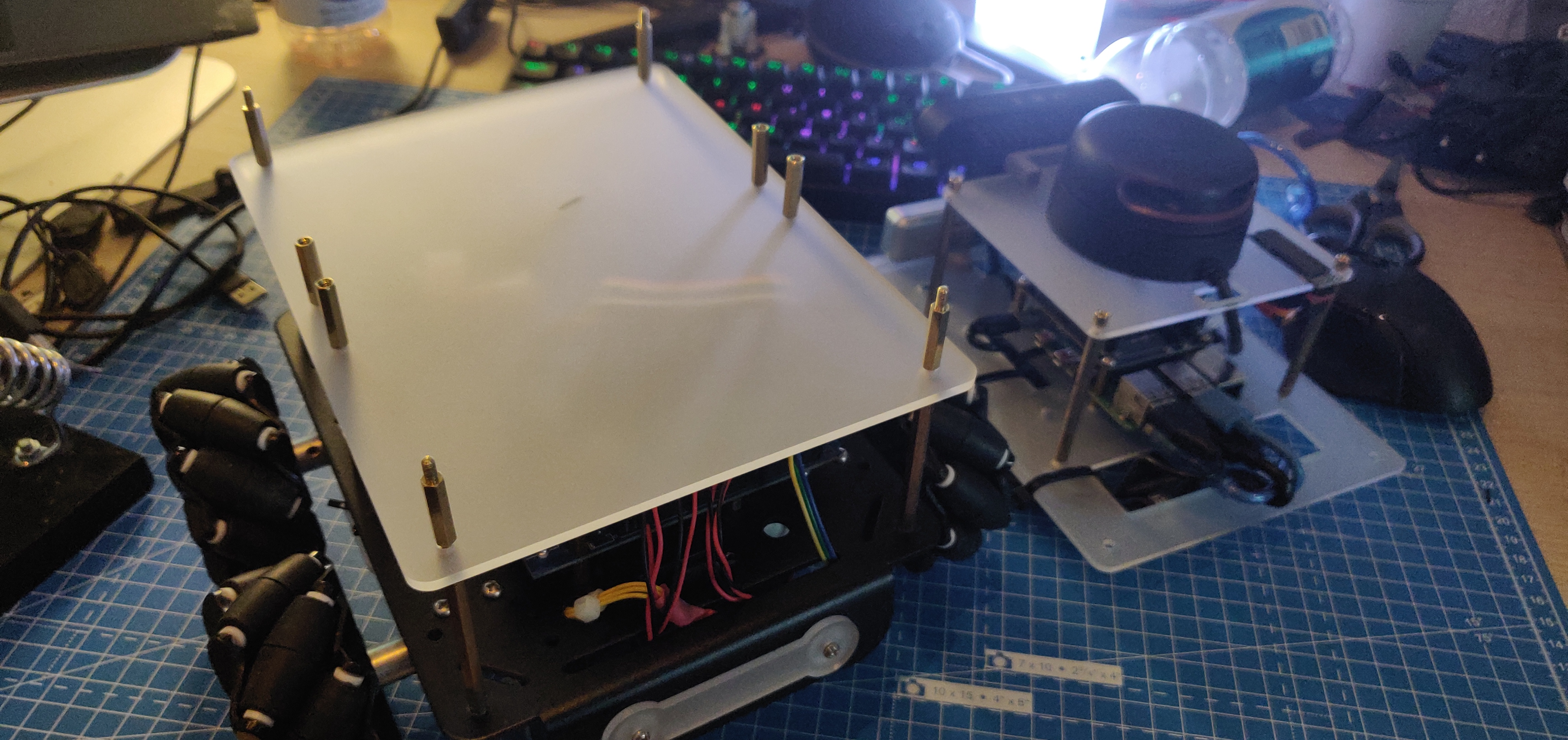
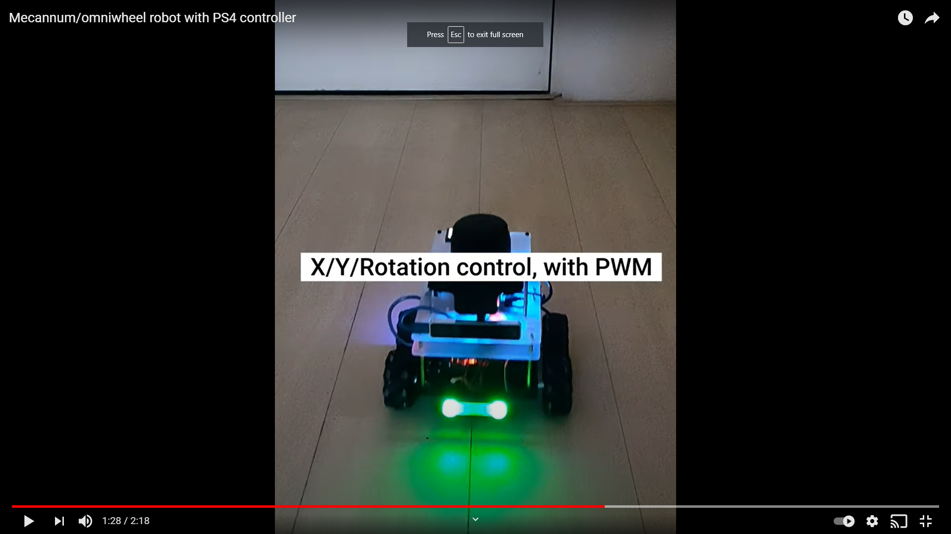
I’ve been on holiday this week, and decided to have a staycation and spare some time working on the AKROS holonomic platform. I got it back from the friend I lent it to, wired it up, tested it and assembled with the navigation module. I am not using the encoders for now, since I have the Intel Realsense T265 to provide some odometry estimates. First, I wrote the Arduino code to drive the holonomic platform (using kinematic equations) taking velocity in x direction, velocity in y direction and rotation around z values as inputs. I made the robot drive along a pre-programmed path to test if everything worked. Since I was also charging the battery at the time, I decided to map the x, y and z values to RGB values for the neopixel headlights on the robot. This let me test the ROSSerial interface without having to drive the motors. I then added a cmd_vel (twist message) subscriber and added the motor/neopixel control functionality to the callback function. Next, I tested if the wiring was correct and assembled the base with the navigation module.
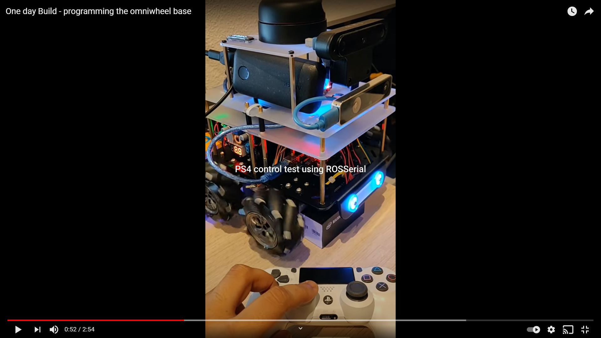
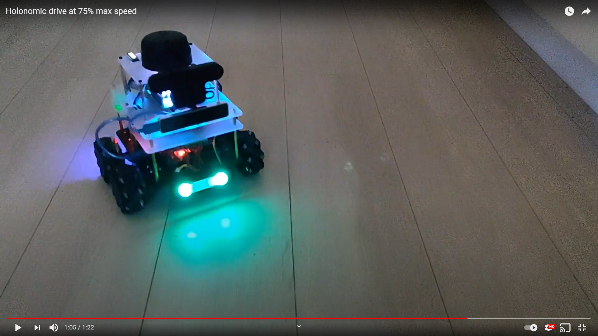
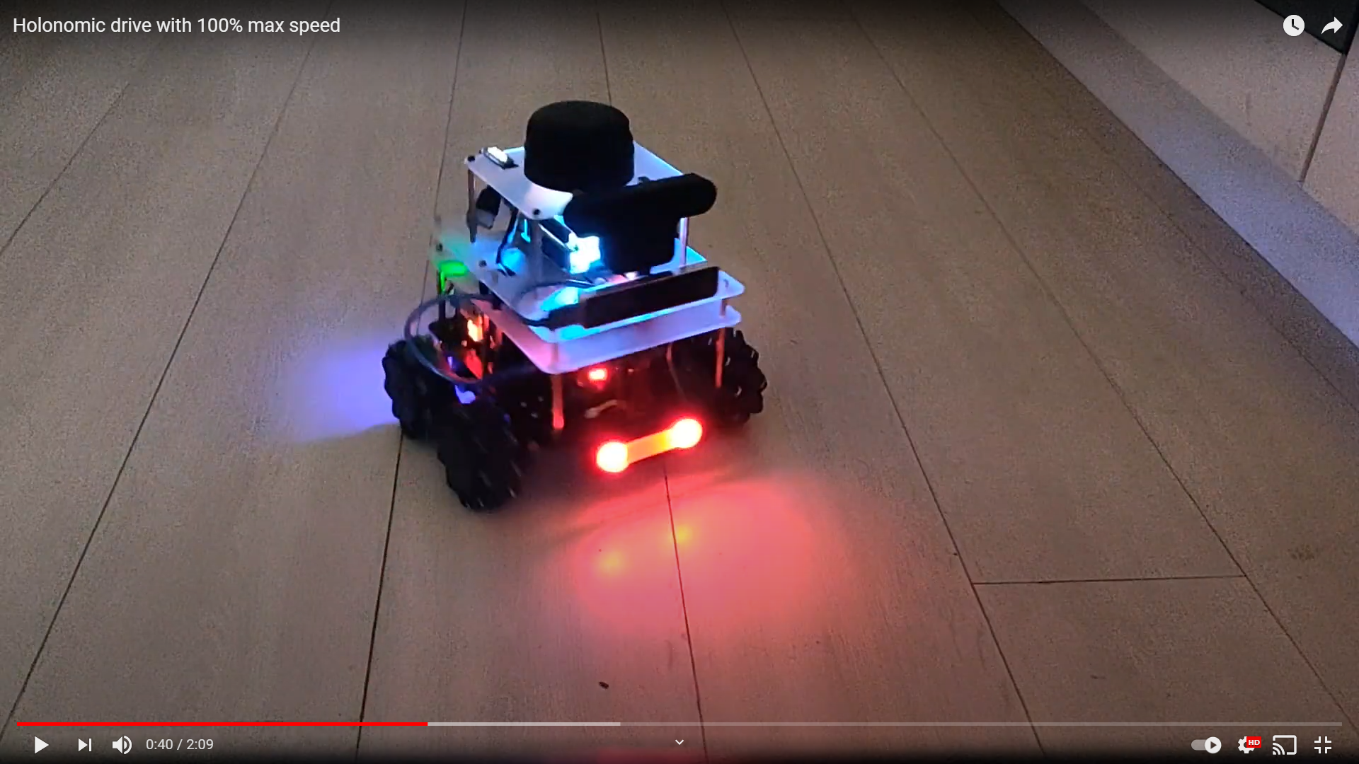
Next, I used the ds4_driver library and the corresponding ROS package to connect the RPi4 with a PS4 controller over bluetooth. Fortunately, for me the ROS package already comes with a twist publisher node. I simply added a 3dof (linear x, linear y, angular z) config file and the twist node was good to go. I also modified the demo node provided to set the PS4 controller’s LED to specific colors according to the input values (R=x, G=y, B=rotation). Now, the PS4 controller’s LED should match the neopixel headlights on the robot. The next step was to add the ds4_driver nodes along with the rosserial_python node in a launch file, and try driving the robot around. I had to tweak the linear/angular gains and max velocity values and finally, I had a platform that I could drive around with a PS4 controller. The following videos show the process and results along the way:
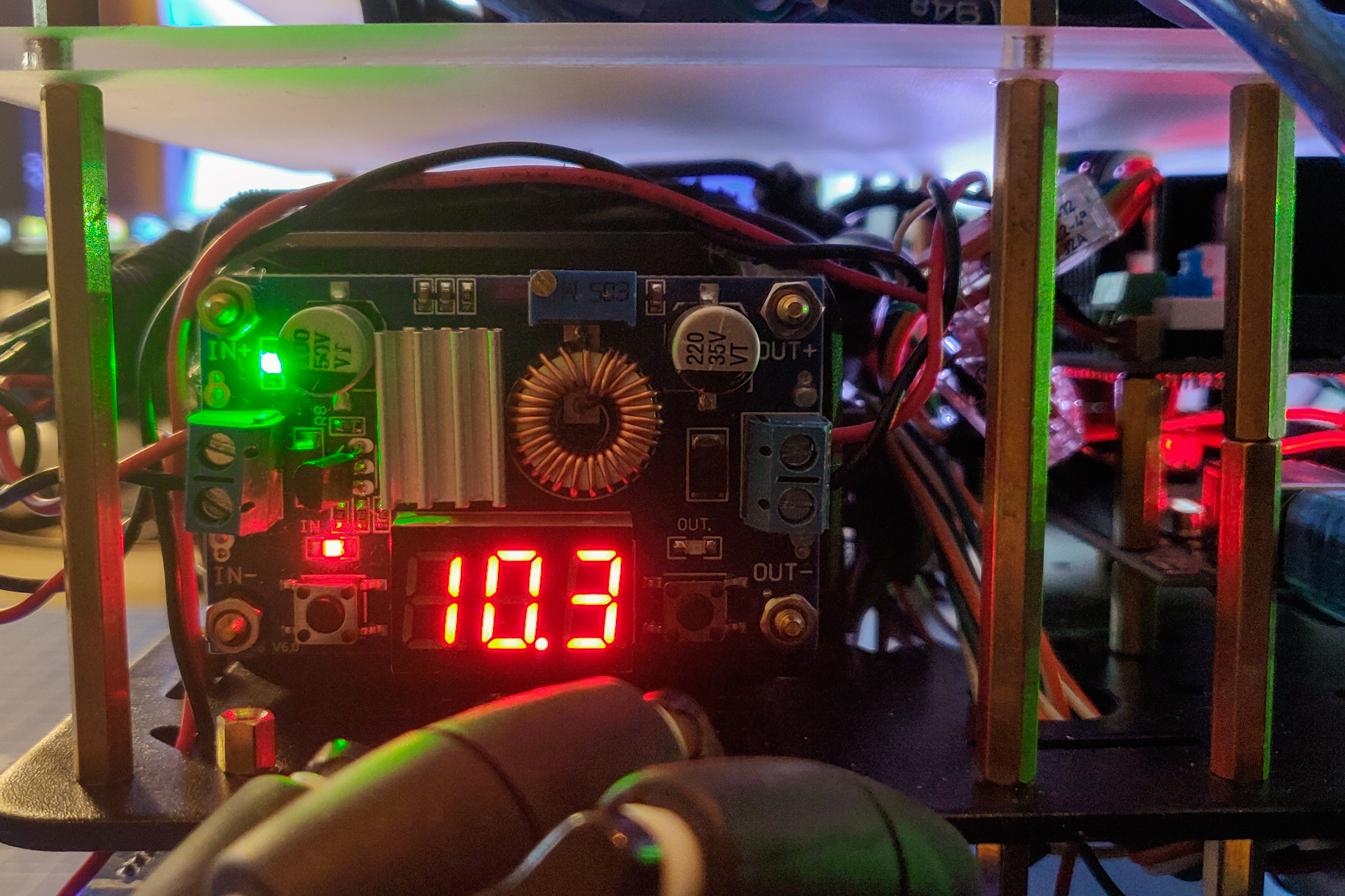
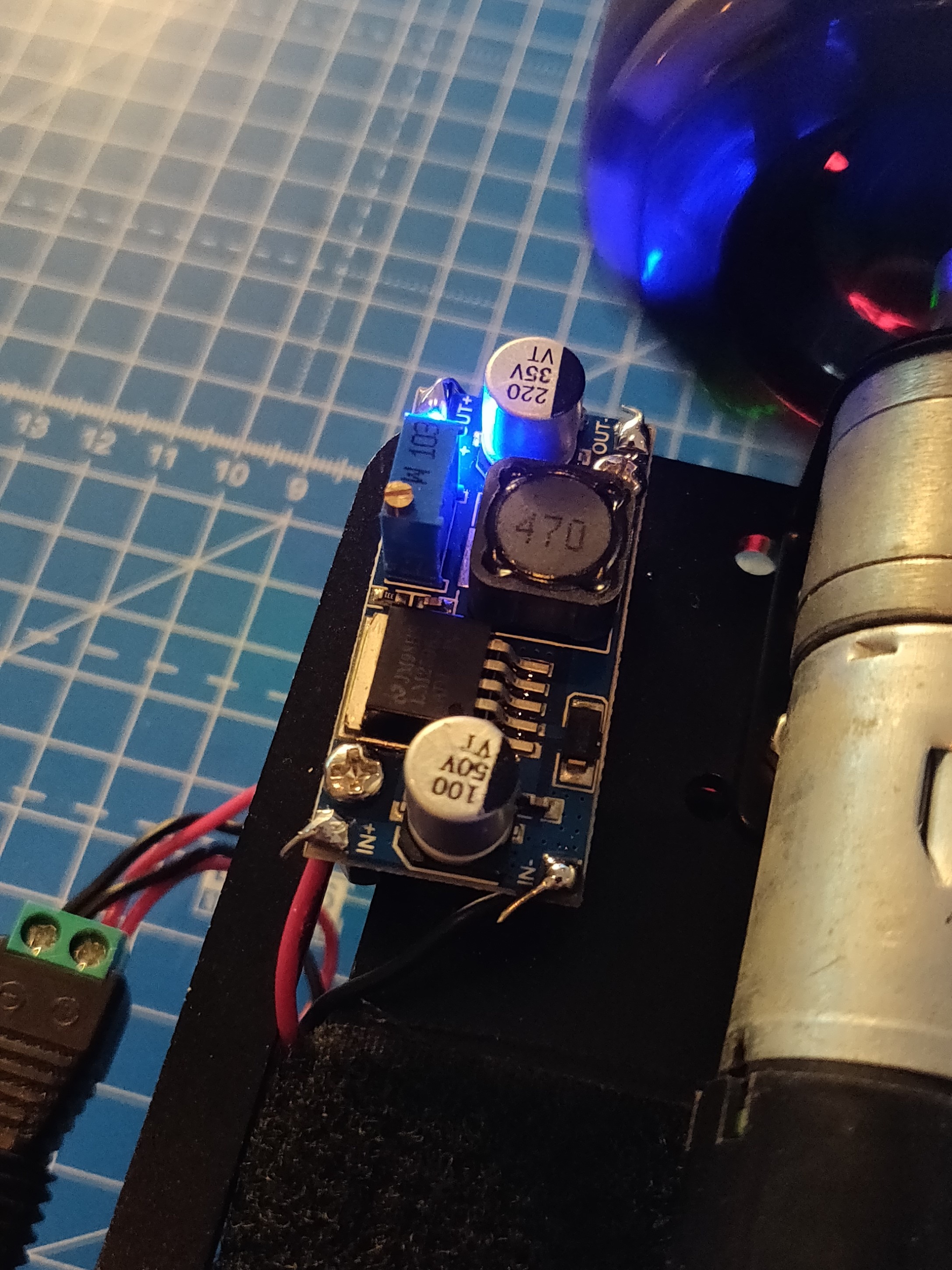
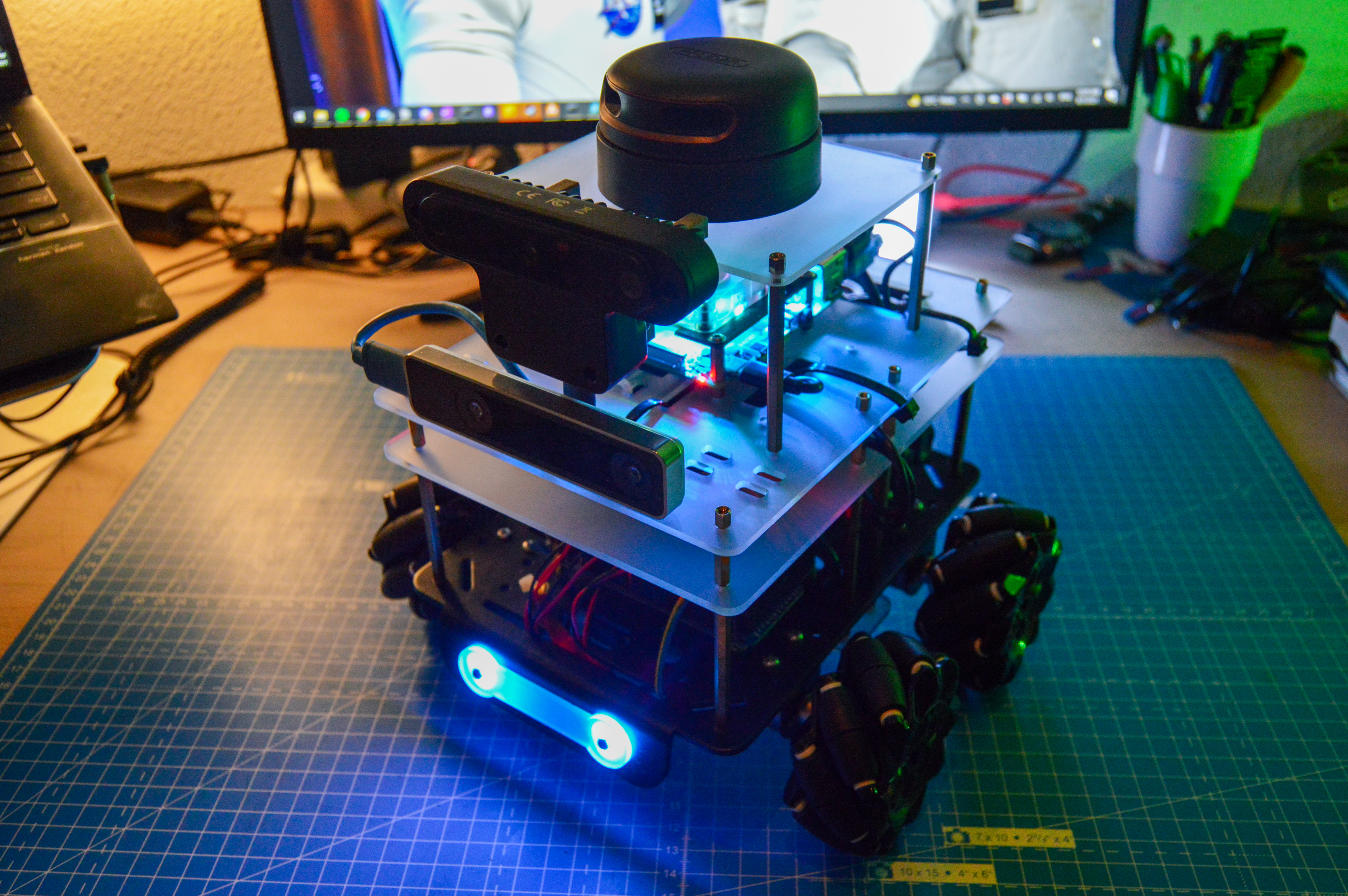
The next step was to run the hector_slam launch file that I had set up some time ago. I modified it so that it also used the odometry provided by the T265 camera. Unfortunately, this is where I faced some issues. The RPi4 is unable to provide enough current to run 4 USB devices. Currently, I have the OAK-D and the T265 cameras attached to the USB3 ports and the RPLidar and the Arduino Mega connected to the USB2 ports. My battery also provides a 5V power supply as a USB output and I have that connected to the DC power port of the RPLidar adapter. I was able to run hector_slam and the drive launch files individually but never together. I decided to get a DC power jack and power the Arduino using the USB 5v port instead. For now, I moved the DC power cable of the RPLidar to my PC’s USB port for testing. Unfortunately, this did not work either. As a last-ditch attempt, I decided to unplug the OAK-D since I wasn’t using it anyway. Suddenly, both launch files could be run together. Success! I even unplugged the RPLidar’s USB power cable and it still worked. This definitely solves my issues for now, but I need to investigate this further because I need the OAK-D in the future. I think powering the OAK-D using external DC power might fix it. If not, maybe moving to a Jetson Nano solves the issue, since it has 4 USB3 ports. Meanwhile, here is a video of hector_slam and the holonomic drive node in action, visualized using Foxglove.
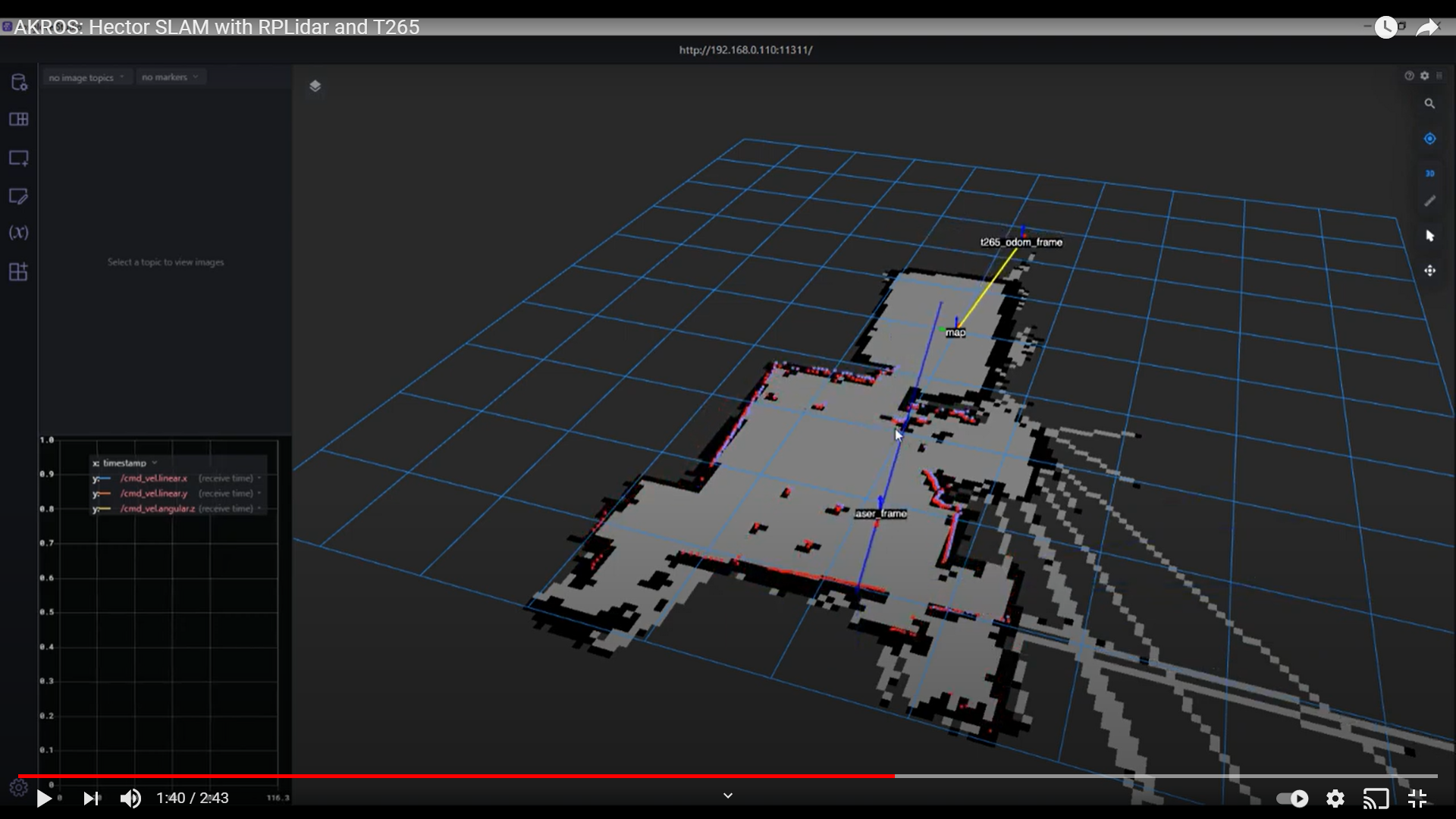 A few interesting things to notice here - first, at between 9-15 seconds, we see the laser scan jump around as the odometry frame drifts. There are a few reasons for this. For starters, I used the camera and ROS nodes as-is. I need to spend some time and calibrate any parameters. Secondly, the room was dark and hence, visual tracking might not be entirely correct. Thirdly, the top panel vibrates due to the driving, which would cause the odometry to drift. I need to fix this using some vibration damping spacers. During the video, you can also see me moving the robot linearly quite a few times. I found this to be incredibly usefule since in my previous experiences, localization/mapping issues have occured mostly due to fast rotations. Finally, at around 2:12, you can see the robot moving back to its origin, and the visual tracking latching on to the position. This compensates for the odometry drift and the odometry frame aligns with the map frame. This is an incredibly cool application, and I’m surprised it took only minutes to set up. One of the reasons why I enjoy working with ROS.
For my next steps, I need to fix the URDF, setup the ROS Navigation Stack (using GMapping, AMCL and move_base; I need to choose between GMapping and Hector SLAM) and meanwhile also fix the OAK-D power issue. I also want to test the battery life of the entire system, for now I can drive around for a solid 30 minutes while also running SLAM on the RPi.