Happy new year! The last week of 2021 was supposed to be a week off in Italy, but it ended up being cancelled, so I decided to spend some time working on the robot. Before I began, I found out the root cause behind the odometry publisher issue. For context, I found that the wheel encoder velocities were not being published by the Arduino. I tried different buffer sizes and baud rates as explained here but I wasn’t able to fix it. I soon realized that the troot cause of this issue was somewhere else - in the twist publisher. The publisher published messages at a rate of 1000Hz, which overloaded the serial connection with the Arduino, hence causing the publisher to stop working. To fix this, I created another node as an interface to the Arduino - it takes care of publishing and subscribing to all data going in/out of the Arduino, and runs at 100Hz. This new node is now able to subscribe to the 1Khz twist topic, and republish it to the Arduino at 100Hz. It can also subscribe to the raw encoder odometry (only velocities), compute the pose and republish this combined information as an Odometry message at 100Hz. The odometry message can then be used in state estimation and localization. This reduction of frequency leads to reduced sentitivity, and a noticeable lag between movement on the joystick, and movement of the robot. Despite this, the robot can still be driven, both in teleop and autonomous modes. I will definitely need to fine-tune move_base and odometry parameters again to get optimal performance.
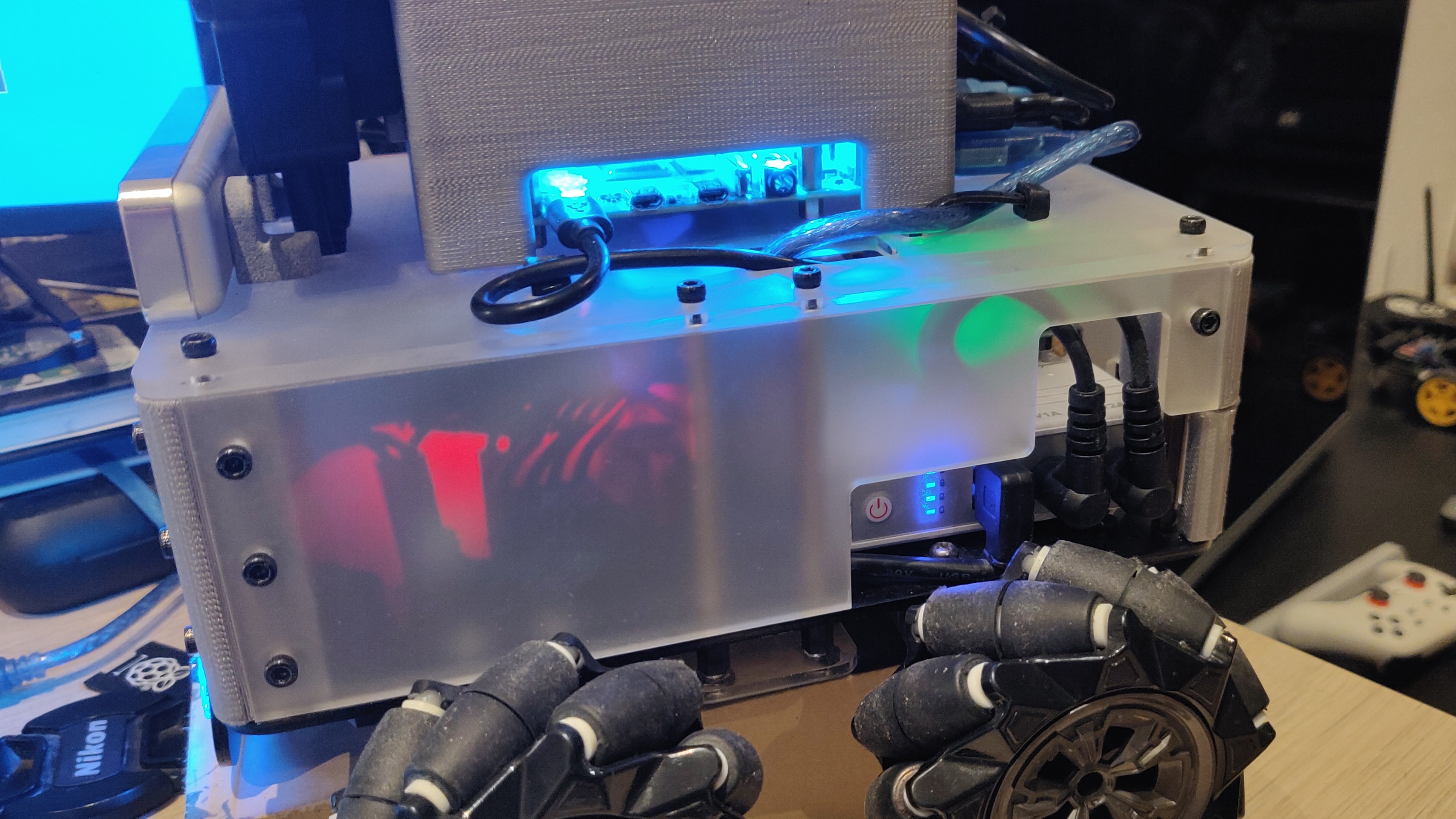
After this fix, I moved to the original plan of making some upgrades to the robot.For starters, the week before I had received some 12V/3A wireless charging modules from DFRobot, but I did not have a 24V power adapter to power the wireless transmitter coil. I decided to order it online, and while at that, I also found a shiny little emergency stop button which would fit quite snugly on the base module. While the parts arrived, I also decided to go ahead and design parts I would need to attach these to the robot. First and the most important change was the right side panel of the robot - I had to make space for the emergency stop button and send the design quickly to Snijlab so that they cut out this new design instead of the first one that I sent them.
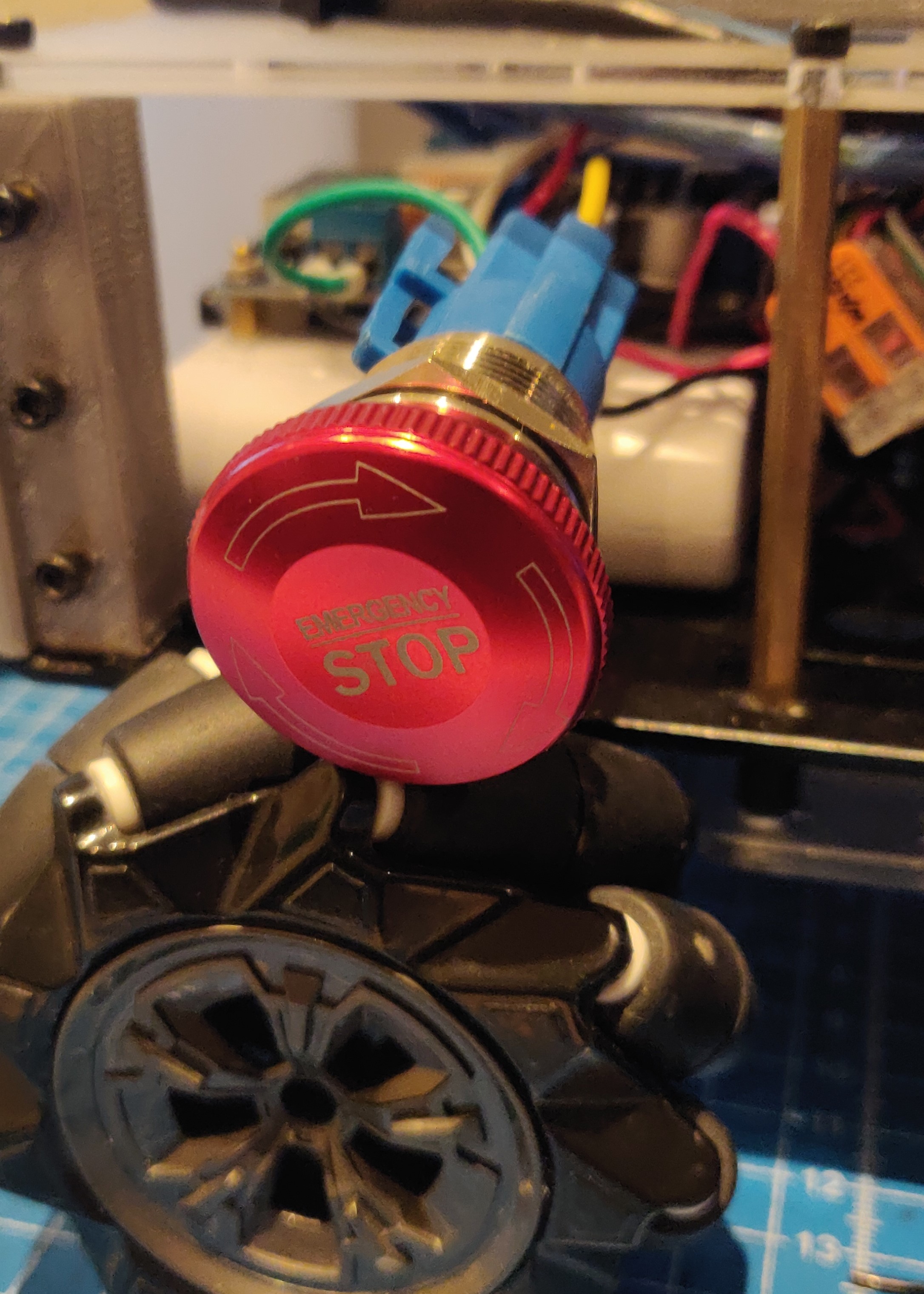
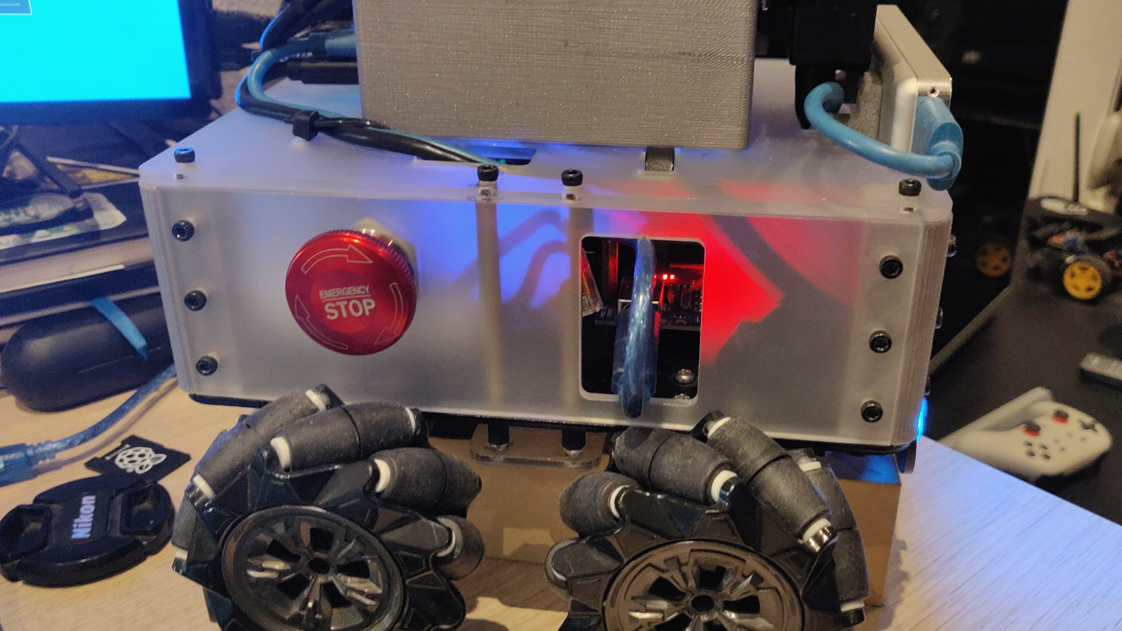
The button was wired between the voltage regulator and motor driver, which stops power to the motors. There is some back current from the Arduino, which drives the motors really slowly when the wheels are off the ground, but once the robot is placed on the ground, it doesn’t move. This of course stops when the twist messages stop, and the arduino automatically stops the motor drivers.
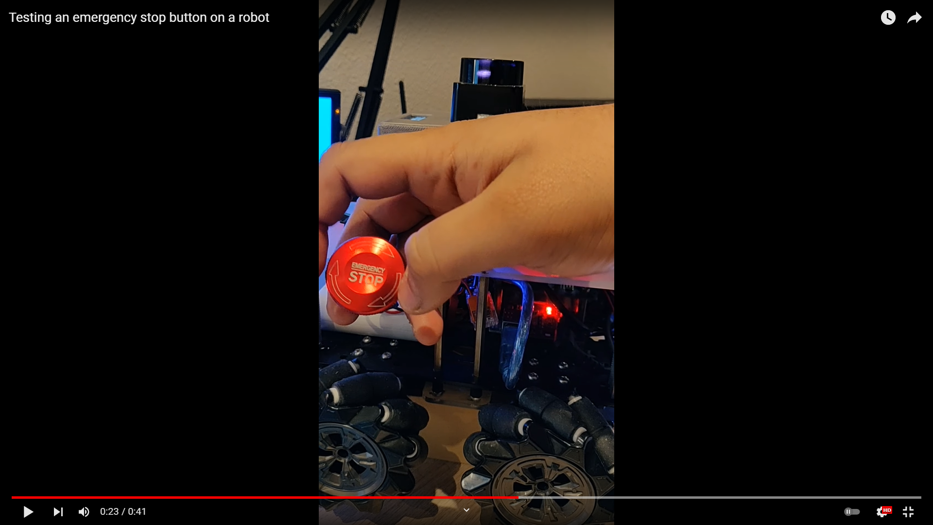
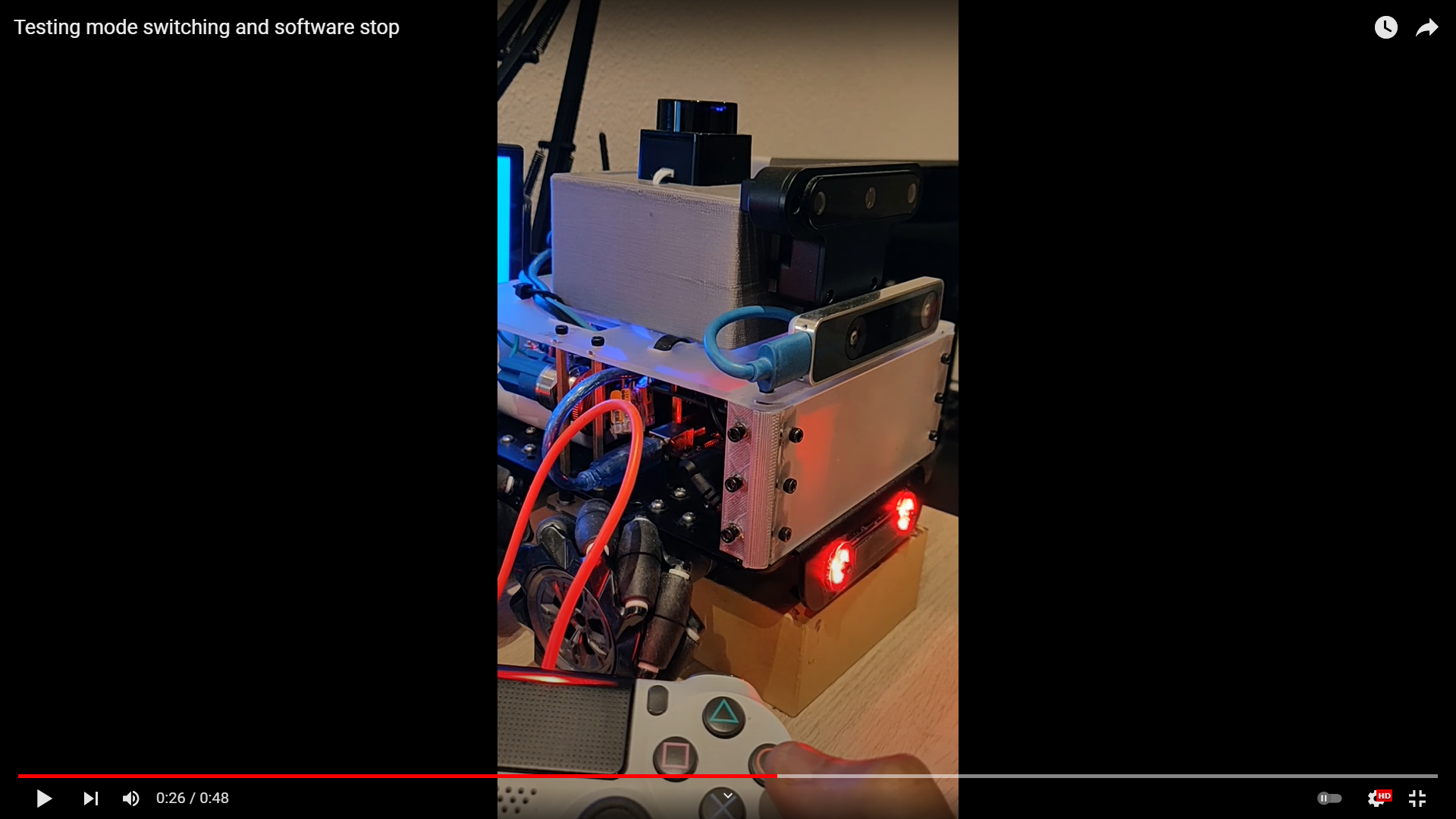
I also decided to upgrade the software emergency stop. Currently, the robot is stopped from software by pushing the red circle button on the PS4 controller which publishes a boolean flag, which is then used by the twist mixer to send twist messages with zero velocities to make the robot stop. However, sometimes the communication is broken and the robot stores the previous twist message and goes wild. But since I now have the Arduino publishers and subscribers fixed, I decided to send the boolean flag directly to the Arduino, so that it can power off both the input and enable pins of each motor when the flag is set to true. I decided to go one step further and send the boolean flags of all the modes (auto/teleop/record/playback/estop) to the arduino by concatenating them into an integer and publishing that instead. This lets me act upon these mode changes from the Arduino - currently the code is set to change the LED colors based on the modes (to match the colors on the PS4 controller). I also decided to use twist_mux and the estop boolean flag as a lock to disable twist messages when the button is pressed. This stops the twist messages from being sent when the emergency stop is pressed, and also disables the input pins for the motors and changes LED colors - so the robot comes to a complete halt without any doubts. Here’s a quick video to show this:
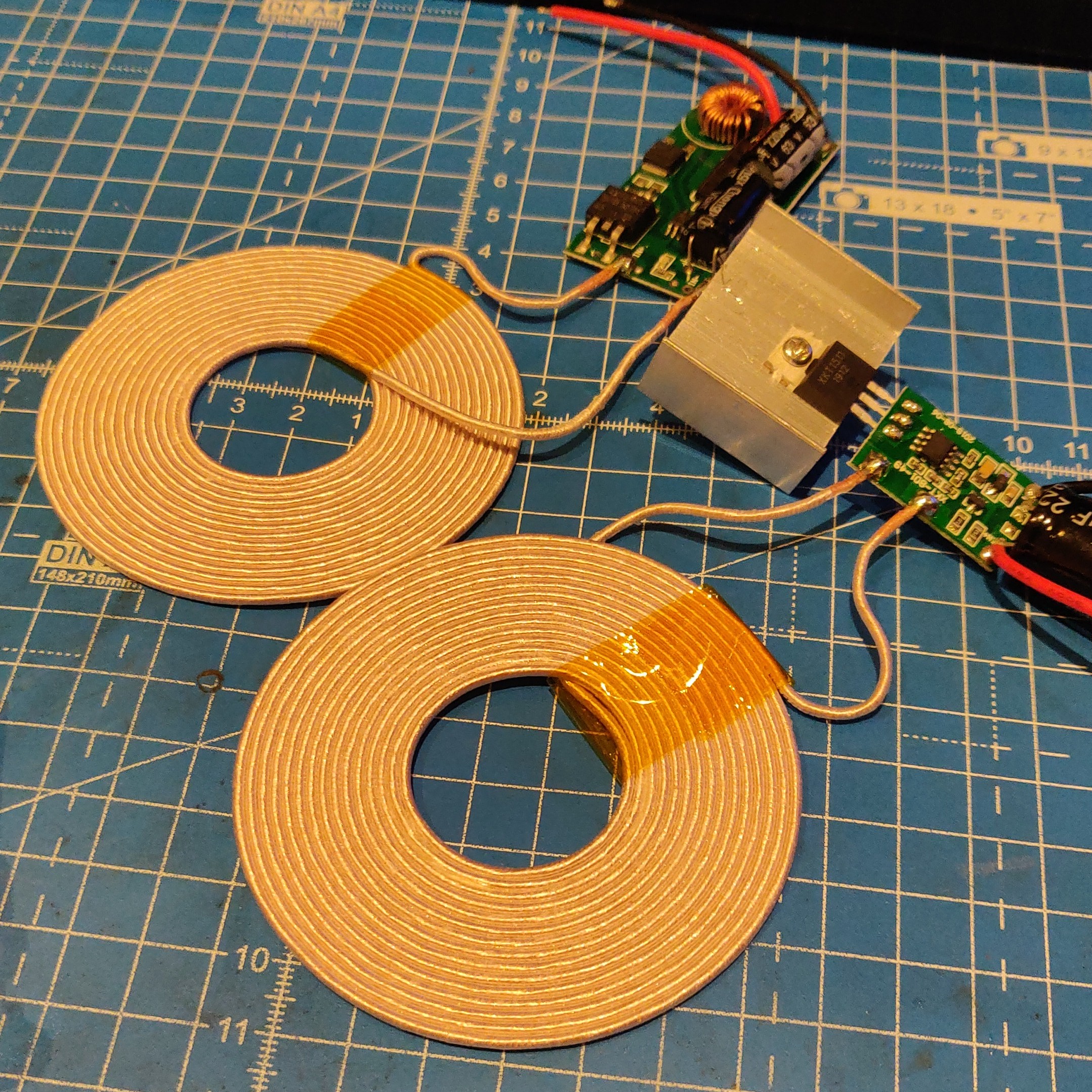
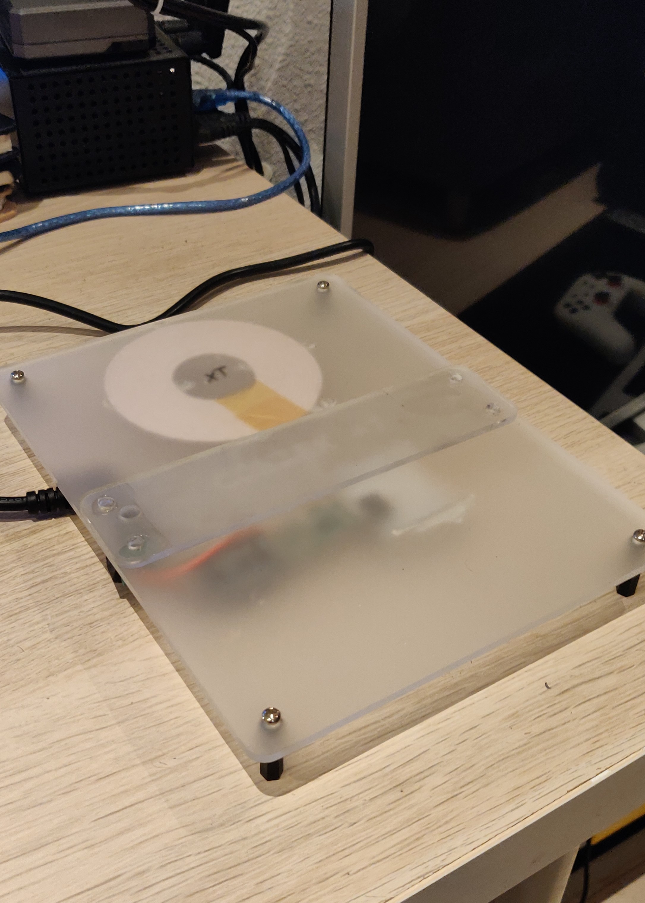
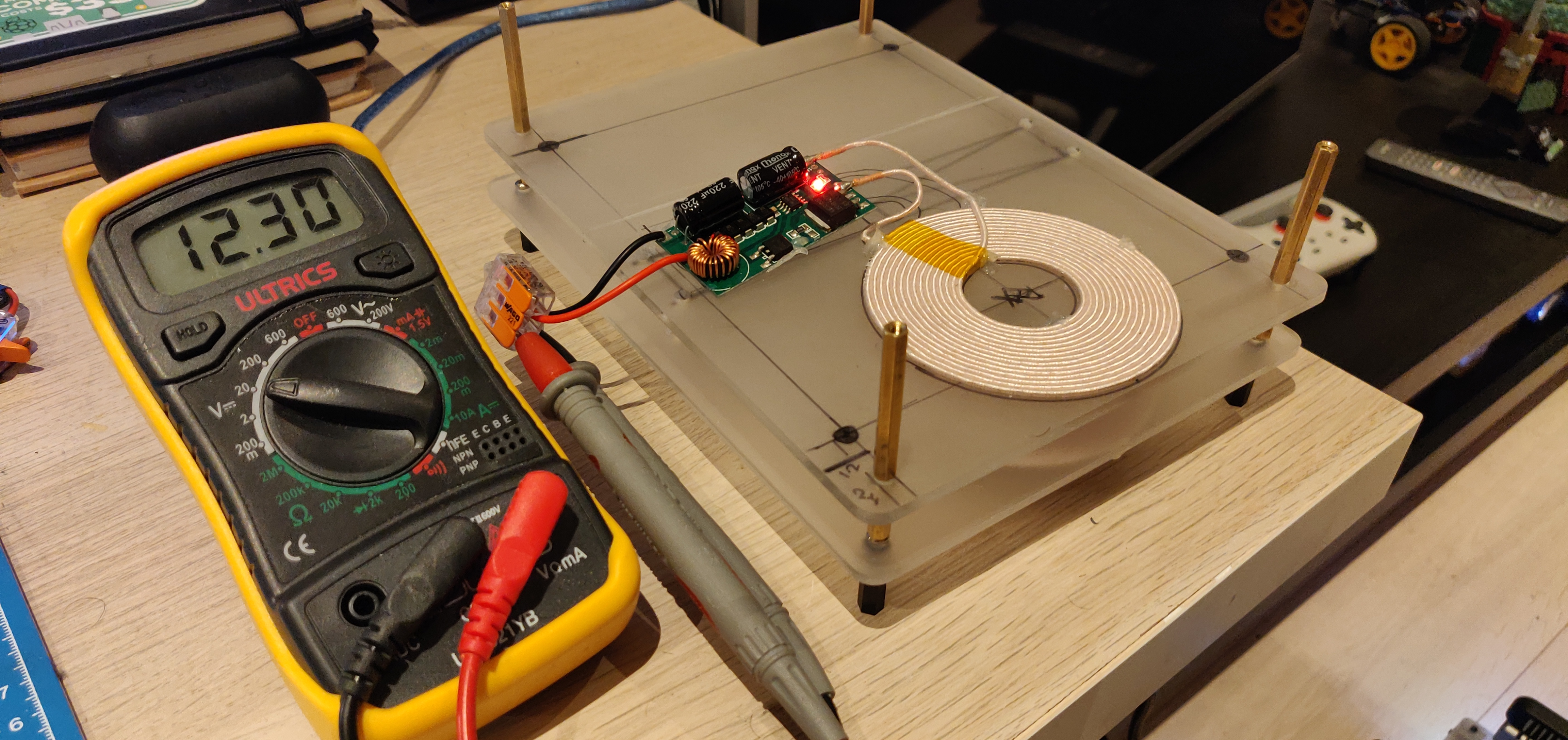
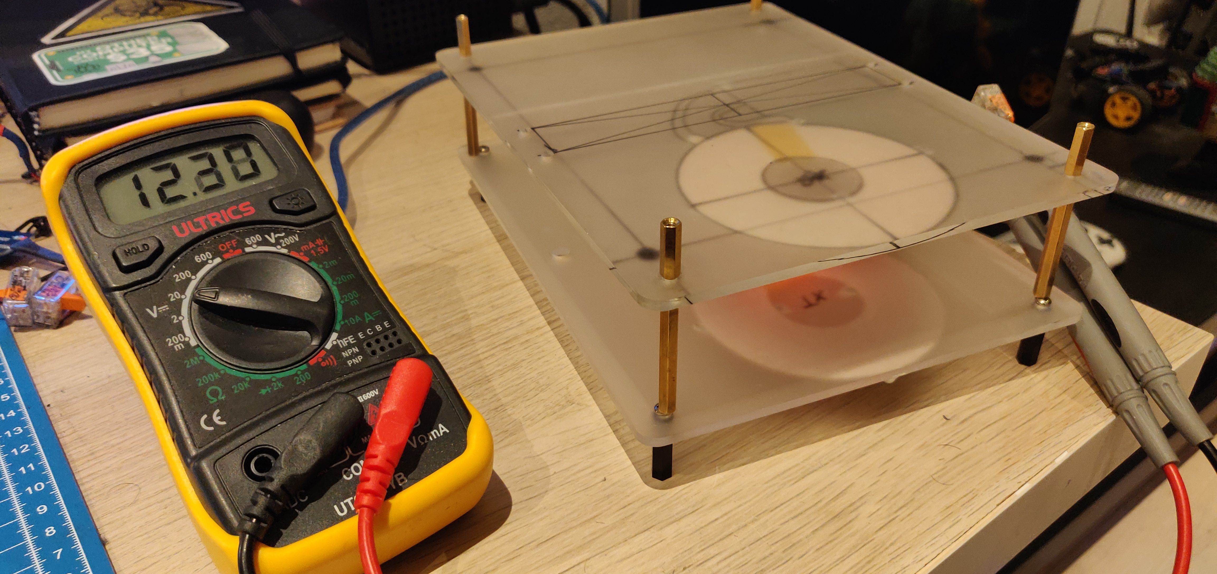
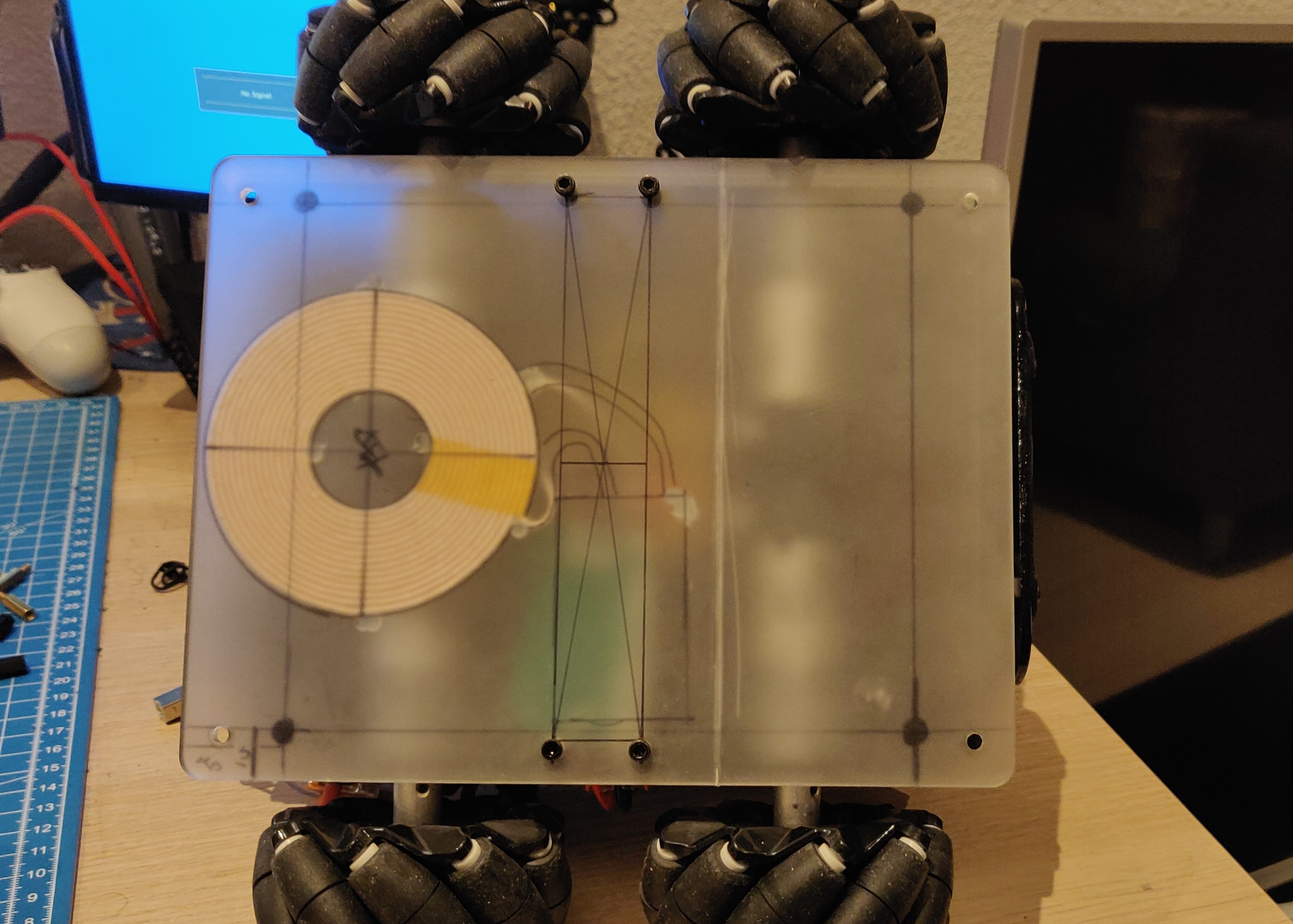
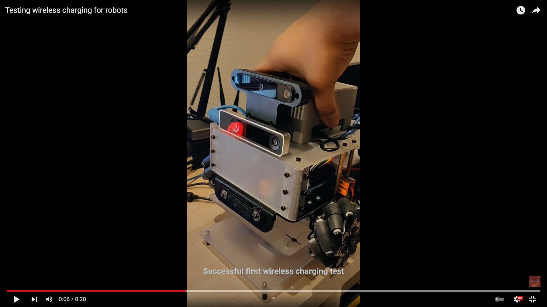
The next step was to design parts for the wireless charging module. I glued the transmitter and receiver modules to two template pieces of acrylic for this prototype. Since these acrylic sheets follow the template of the base plate of the robot, it has holes in the right places, so I could simply screw it underneath to the robot with some spacers. Meanwhile, I received the power adapter so I could put the system to test. And I was blown away by how efficient it was. I could keep the coils apart, parallel to each other at a distance of up to 6cm and still be able to receive 12V/3A. In the horizontal plane, I was able to receive the required power even with an offset of at most 3cm. Since the voltage is already regulated on the receiver module, I plugged it directly to the input port of the UPS/batter onbooard the robot and did a little test.
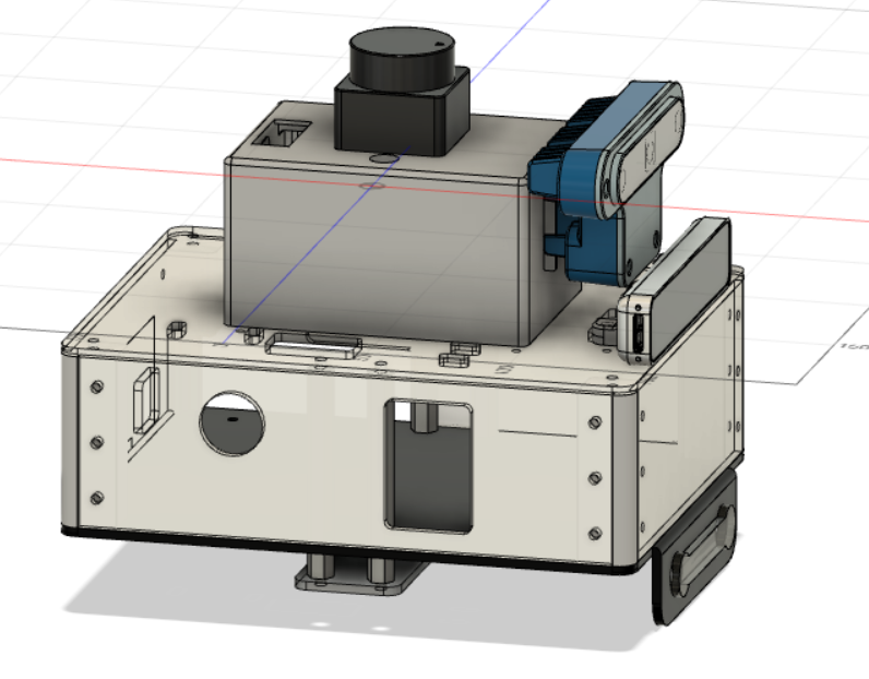
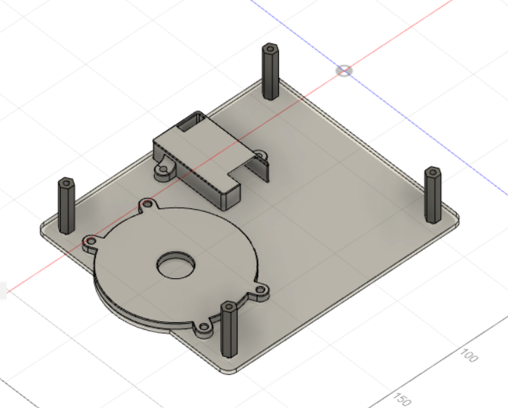
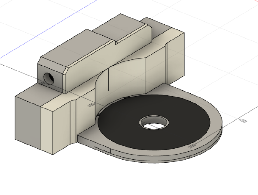
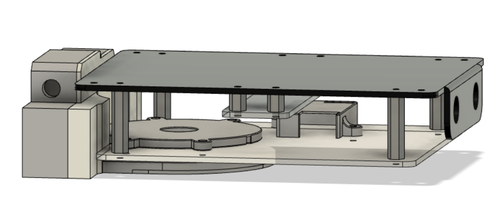
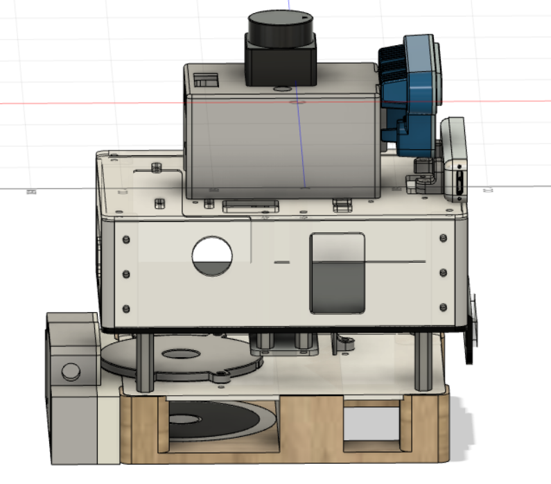
I then went on to design the parts I would need in Fusion 360. The receiver module that fits onto the robot has three parts, an acrylic base plate to hold everything, and two 3D printed covers for the coil and the receiver module. I’ve left enough space for a voltage regulater (if needed) and space for an RGB LED and a small microcontroller to light up the LED when charging. The acrylic piece also has a curved end, which fits into a notch on the transmitter module.
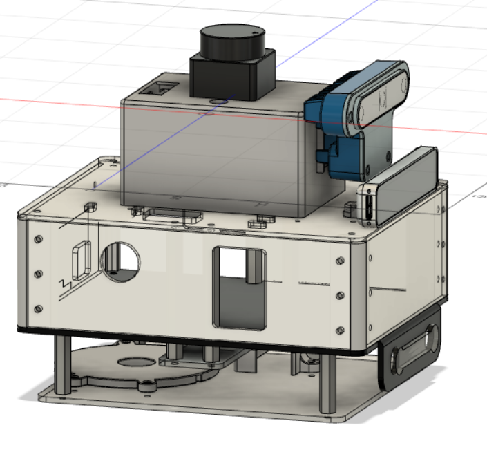
The transmitter module is also made up of 3D printed and laser cut acrylic parts. They hold the transmitter module, the transmitter coil, a female socket for the power adapter plug. This module also has a curved notch where the receiver module of the robot can simply fit into. I’ve also designed a stand for the robot, which I can use for testing. This hopefully will be CNCed in wood, if the workshop I’ve been meaning to attend finally happens in 2022. There are also notches on the transmitter module where this stand and the robot can fit into. This notch method keeps the transmitter and receiver coils perfectly aligned when the robot is on the ground or on the stand and maintains enough distance between the transmitter and receiver coils to allow for charging.
While designing these parts, the acrylic side panels arrived. As expected, the parts fit in snugly. However, in the next iteration, I would probably opt for matte black acrylic instead.
For my next steps, I dont have a lot planned for the next few weeks. I have to finalize the CAD design, get everything 3D printed or laser cut. I still need to do more tests with the wireless charging modules, since the receiver coild is so close to the motors and the hall effect sensors. I’m afraid it will interfere, but in any case, I do not need to use the encoders while charging. Unfortunately, I still need to drive the robot to dock/undock, which might be a problem. Next weekend, I also want to write a long blog about everything I was able to do and learn in 2021. After that, a Covid booster shot and some proper time off.