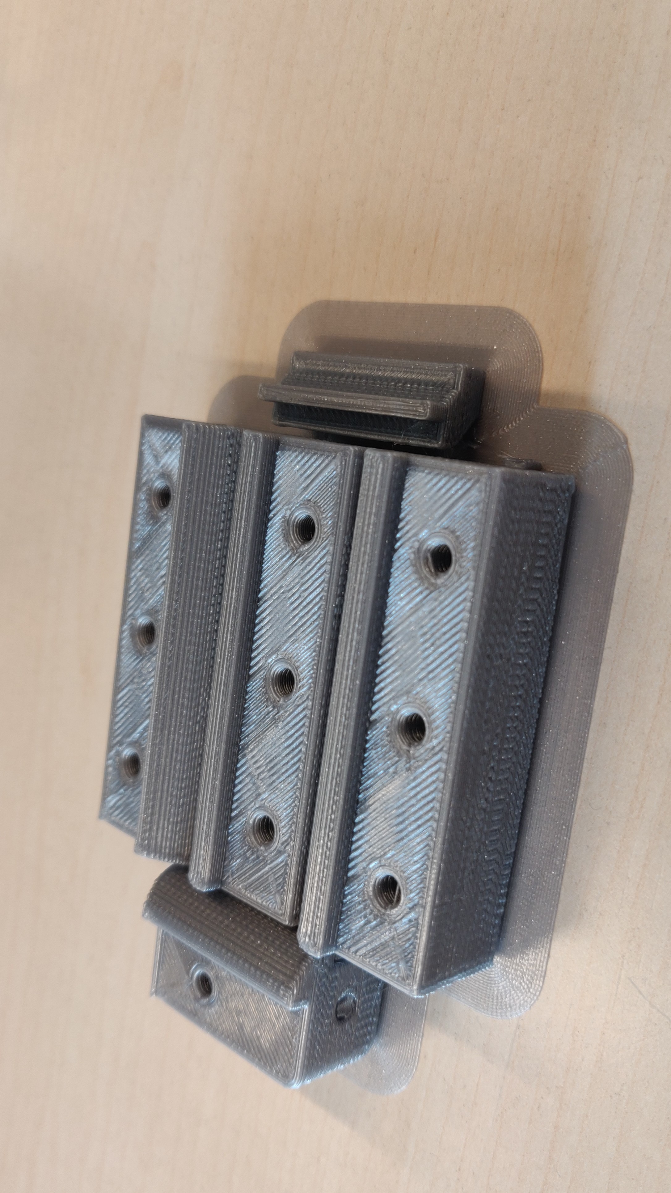
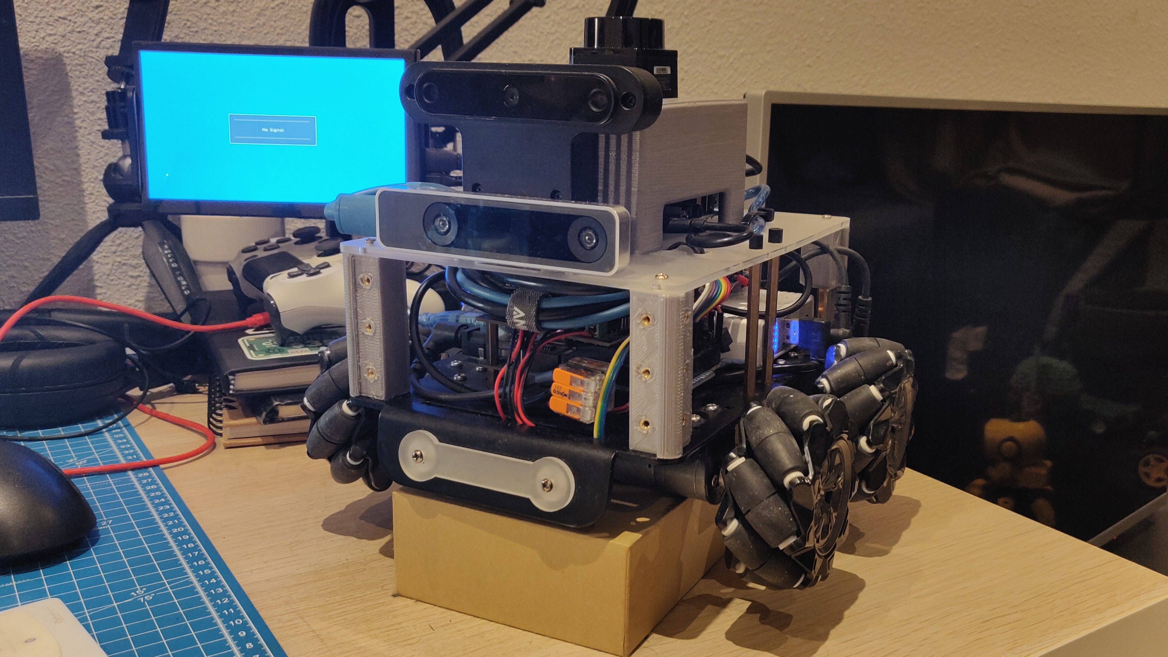
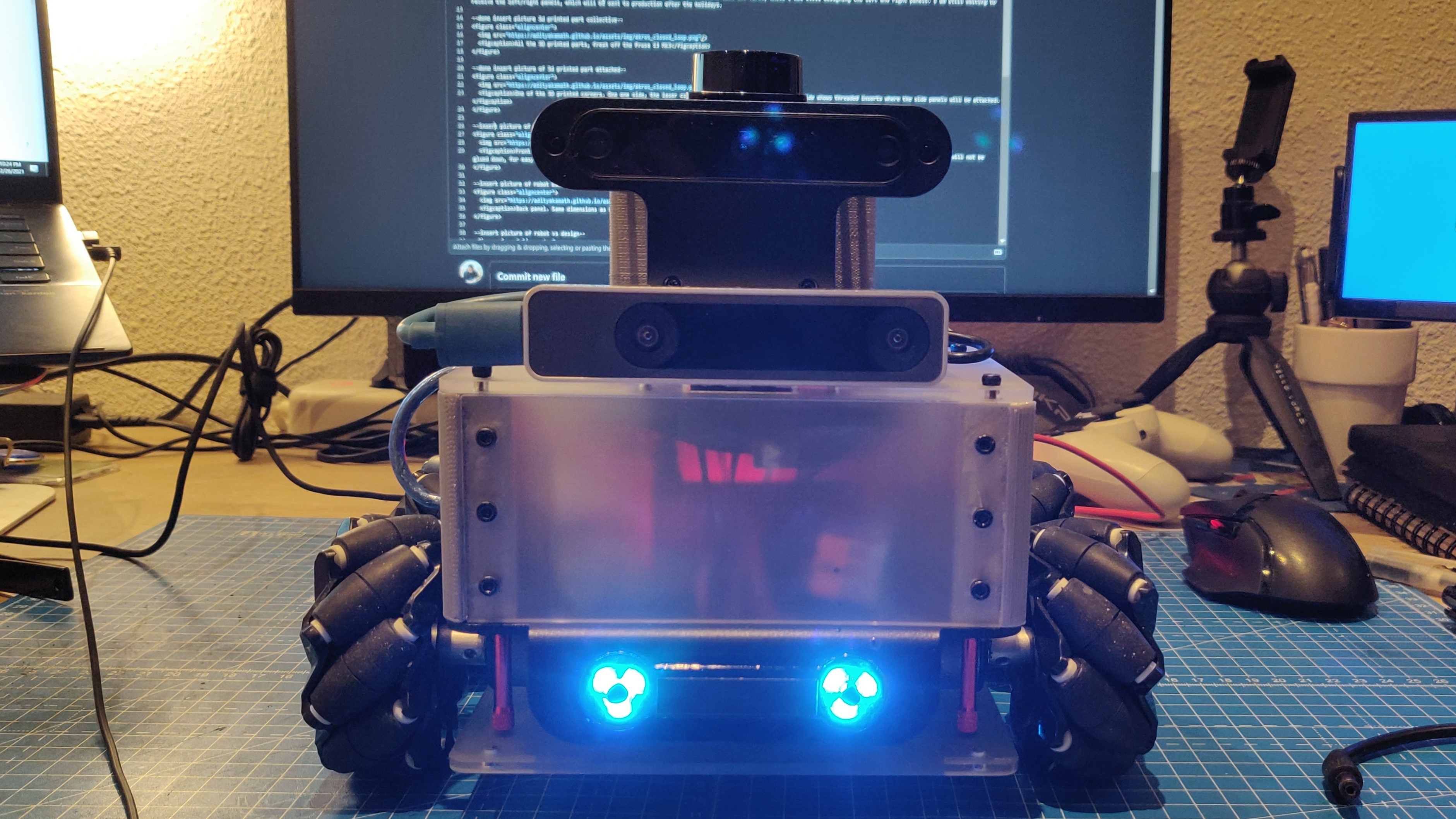
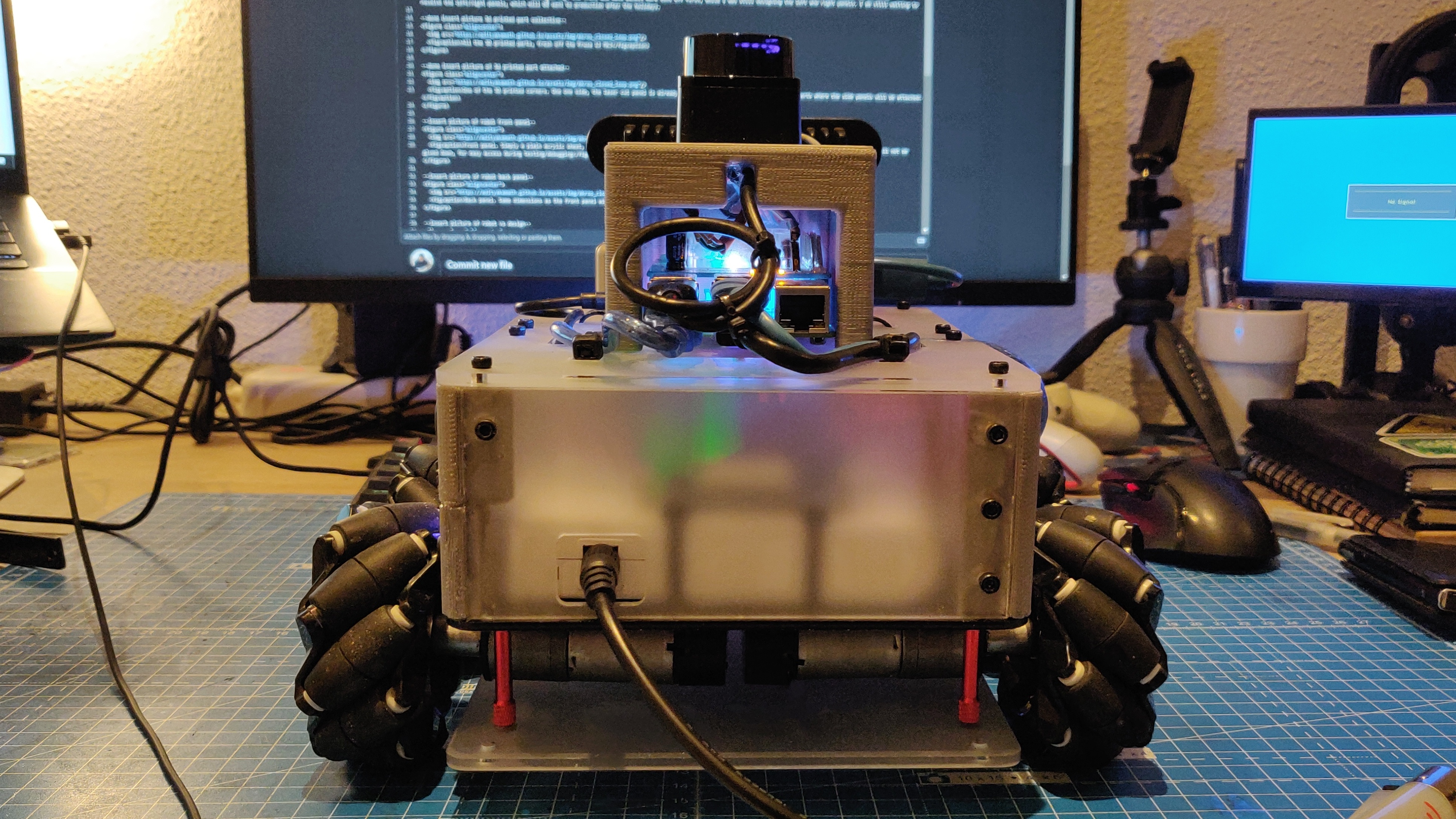
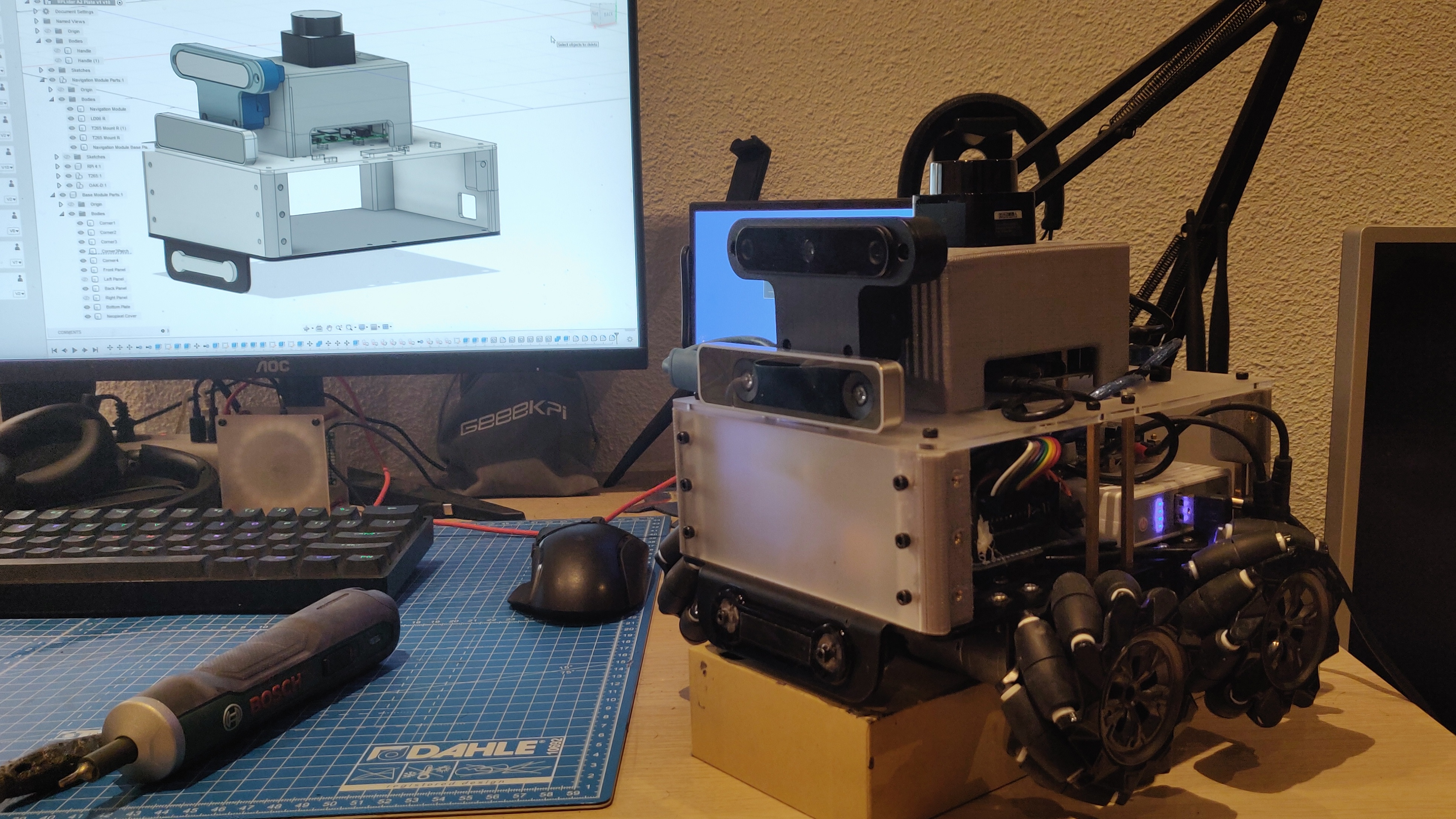
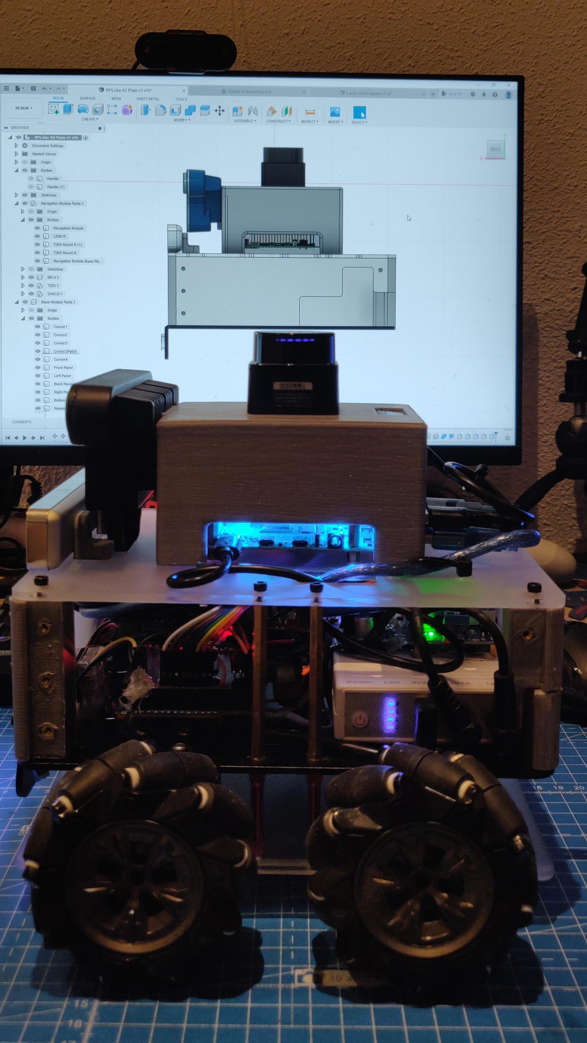
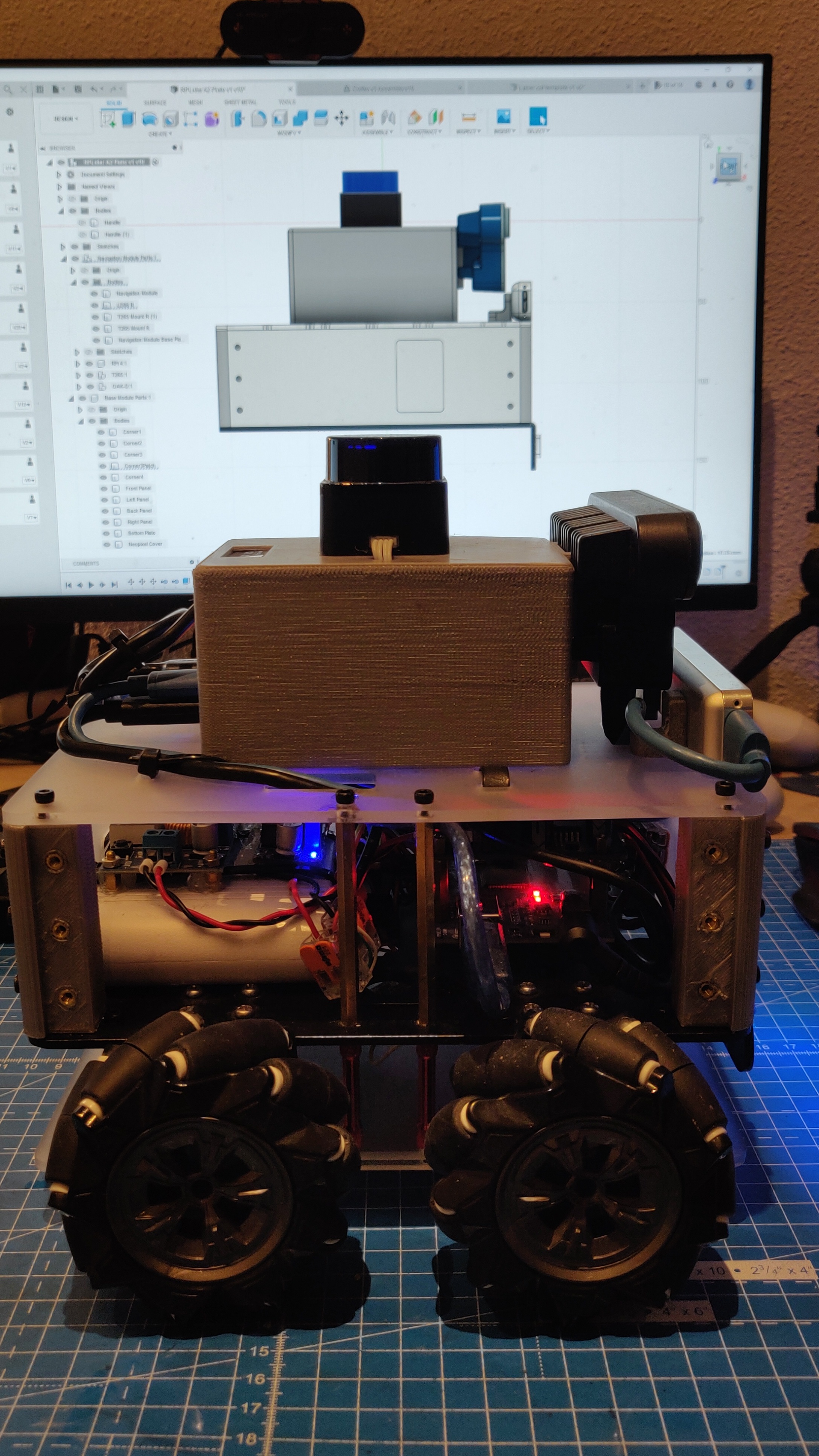
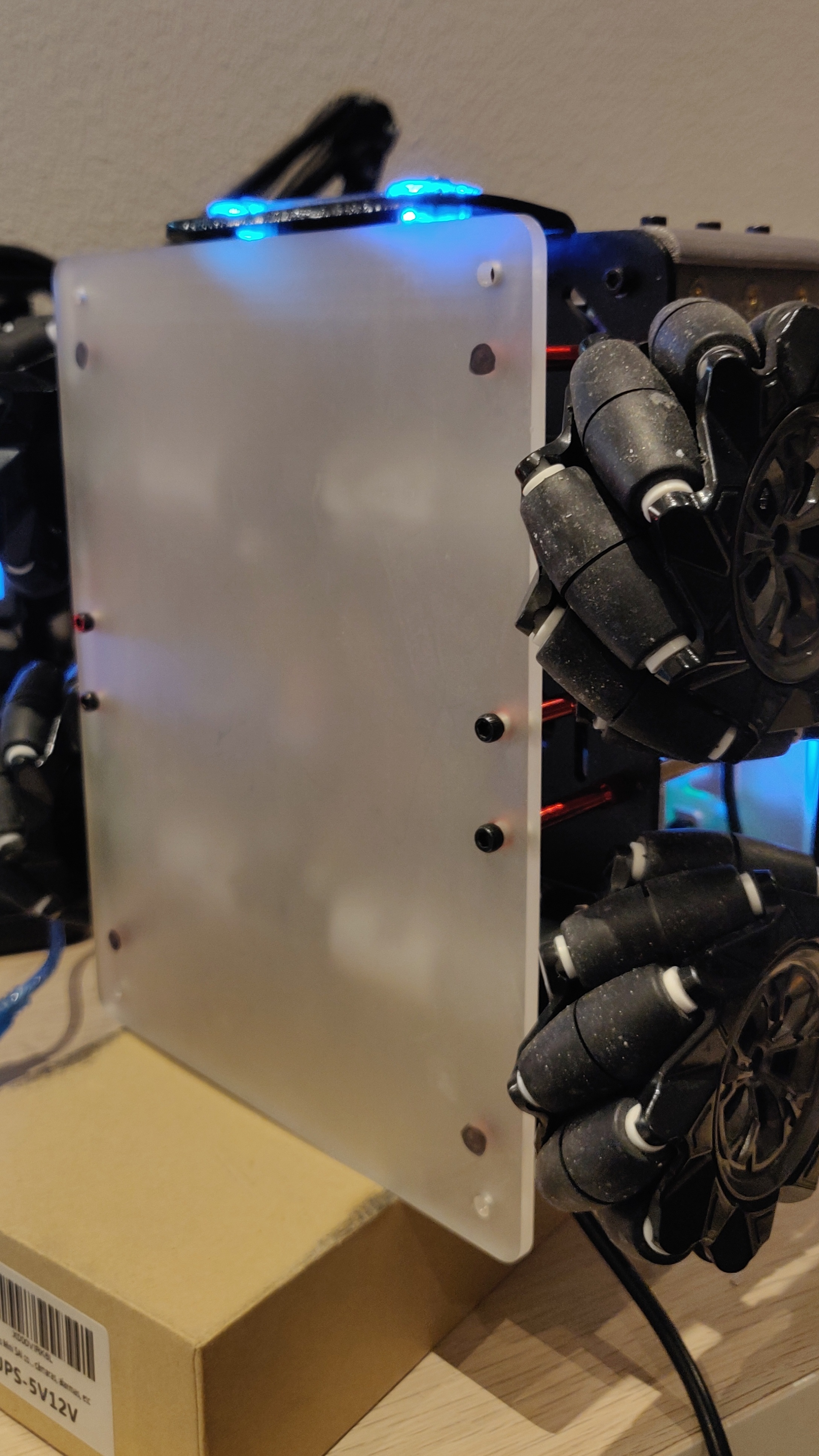
A few weeks ago, I designed a new enclosure for the bottom half of the robot. I designed it for a CNC machine, since I was supposed to attend a CNC workshop in December. Of course, this was cancelled because of the pandemic, so I decided to 3D print it instead. Unfortunately, the part was too big and the print was estimated to take at least 12-15 hours. So the next step was to go back to my favourite prototyping tool - a laser cutter. I simplified the design so that I had four laser cut panels - one for each side (the top is covered by the navigation module panel, and the bottom is covered by the robot), and 3D printed parts to hold these four panels in place. The final 3D print took less than 3 hours, and after using a soldering iron to add threaded inserts, they were ready to go. Since the laser cutter at work cannot cut acrylic, I sent the parts to Snijlab.nl for manufacturing. The front and back panels were sent off first, while I was still designing the left and right panels. I am still waiting to receive the left/right panels, which will be sent to production after the holidays.
This done, I next moved on to the OAK-D IMU. Initially, I had thought of passing the output values through a filter to get rid of the noise, but turns out it wasn’t needed after all. The DepthAI API lets me access calibrated and gravity-compensated IMU values, so they are already filtered. I did however pass them through the robot_localization node with an Extended Kalman Filter for now. This does not provide any improvements, but when I fuse it with wheel odometry, I can just add that to the robot_localization parameters. About the wheel odometry, I was unable to fix the publisher from the Arduino. I tried almost all combinations of buffer sizes and baud rates, but the publisher still has the same issue - it publishes messages for a while, then stops. I hope moving to ROS2 and microROS fixes this issue, but I also intend to use a Teensy instead (a potential PCB design project) sometime in the future. Teensies are much more powerful and should definitely be able to publish and subscribe to multiple nodes at the same time. In my current OAK-D node, I publish the RGB images, depth images and the IMU data, but as I’ve previously found out, I cannot run both this node and the navigation stack at the same time. It makes the entire system extremely slow. Now, since I want to use only the IMU with the navigation stack, I created another node for publishing IMU information only. This does not slow down the navigation processes, it should in fact improve navigation once the odometry and OAK-D IMU are fused and this is used to replace the T265 visual tracking. Then, the Visual SLAM can be implemented using RTABMap, DepthAI Feature Tracker, or other methods such as OrbSLAM3.
Next, I took my first real steps with the ROS2 porting. I installed ROS2 Galactic on my Raspberry Pi 4, and setup the ROS2 workspace and all necessary environment variables and aliases. I installed everything on root, but I’ve read that is much better to containerize different environments using Docker. I plan on attending a workshop conducted by my office and try this out on my Jetson Nano (which I use as a ROS ground station), where I cannot install ROS2 natively anyway. I then installed ROS1-2 bridge and setup a tutorial publisher/subscriber between ROS versions, which worked like a charm. I am slightly annoyed that the bridge does not allow you to see ROS1 topics under ros2 topic list, but I know people are working on it, perhaps this feature is implemented in future distributions of ROS2. For now, the bridge works, ROS1 messages are accessible by ROS2 nodes and vice versa. This means I can start porting things one by one to ROS2 without breaking the robot’s functionality.
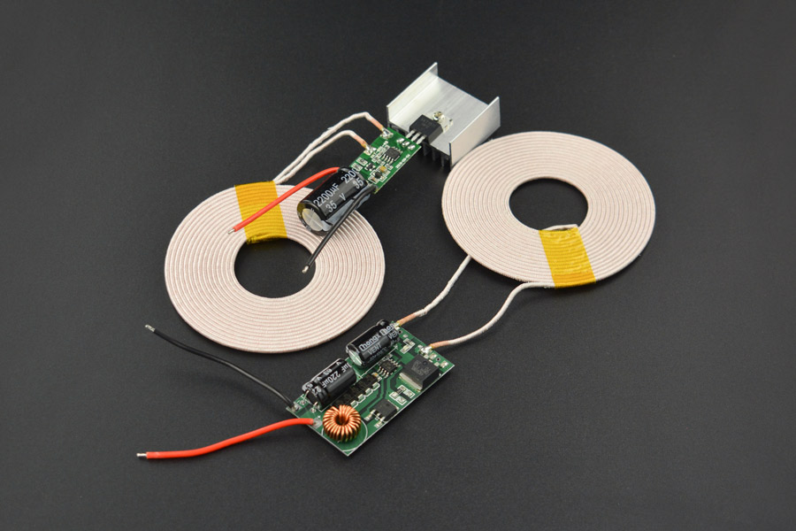
Finally, it was time to take some time off for Christmas, finish things up with the robot and then head off to Italy to spend the New Years. But thanks to Omicron, this trip had to be cancelled, and a lockdown was announced in the Netherlands till the middle of January 2022. While I was downloading games and making a list of movies to watch, I also found a 12V/3A wireless charging module and ordered it. I’ve always wanted to build a docking station for the AKROS robot, wireless charging is probably the easiest way to do this, since I dont need to design or add latching mechanism for a wired power connection. All I need to do now is build a plate on the bottom of the robot where the receiver module can be mounted and this can be wired to the UPS/battery on the robot. I already have a spare blank base-plate template, which I attached to the bottom of the robot, which I will use to prototype the bottom plate once the wireless charging module arrives. Now, after the cancelled plans, I will have enough time to design the parts during my holidays and then get them printed at work in the first week of January. So at least there is a silver lining to all this.
So, for the next few weeks, my job is quite limited and easy - wait for the side panels from Snijlab and then assemble it onto the robot, play with the wireless charger and design mounts for it, then 3D print and attach to the robot. I also will write another post in January about all the progress I did in 2021, and my plans for the 2022..I do have some big things lined up.