A few weeks ago, I designed a wireless charging module in Fusion 360 to implement the DFRobot 12V/3A wireless charging module on my robot. Over the last two weeks, I finally got to manufacture these parts. This period have been the most I’ve visited my workplace in almost a year. Mainly because I decided to 3D print the entirity of the wireless charging module instead of having some parts laser-cut. This meant that I had to make multiple trips to the office to setup or collect 3D prints. But after a few overnight prints, the parts were finally ready. Together, they make two components - the wireless charging transmitter and the wireless charging receiver.
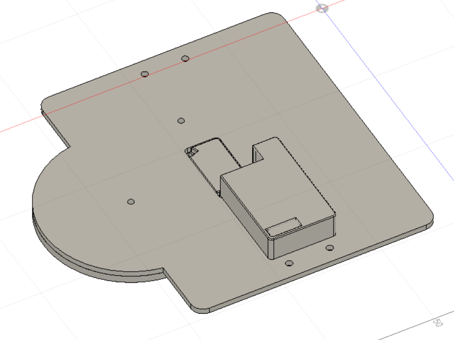
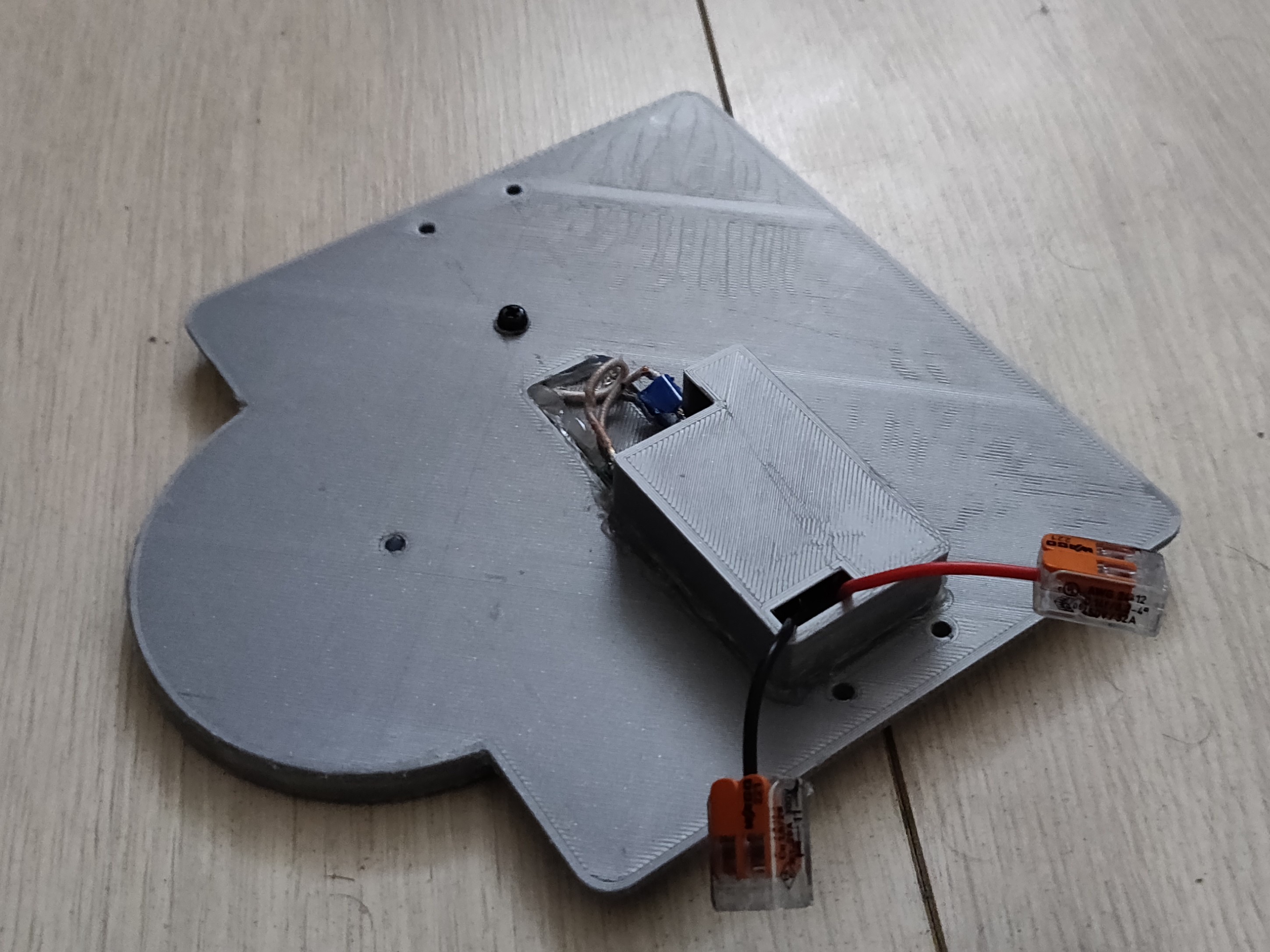
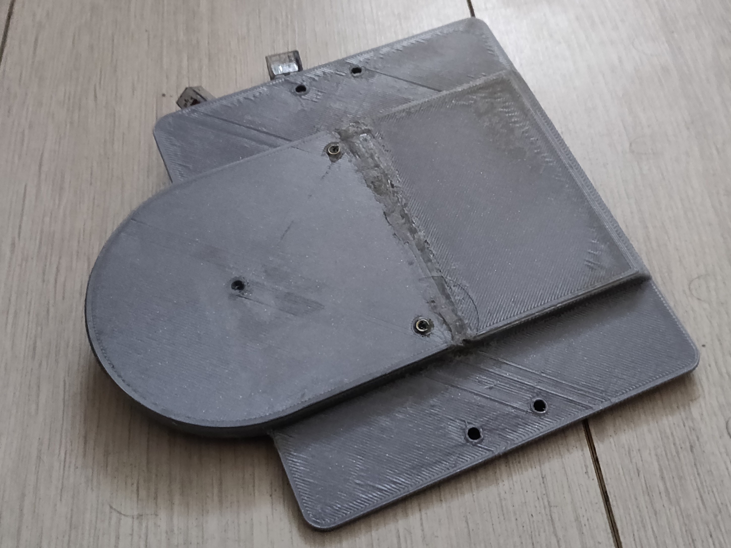
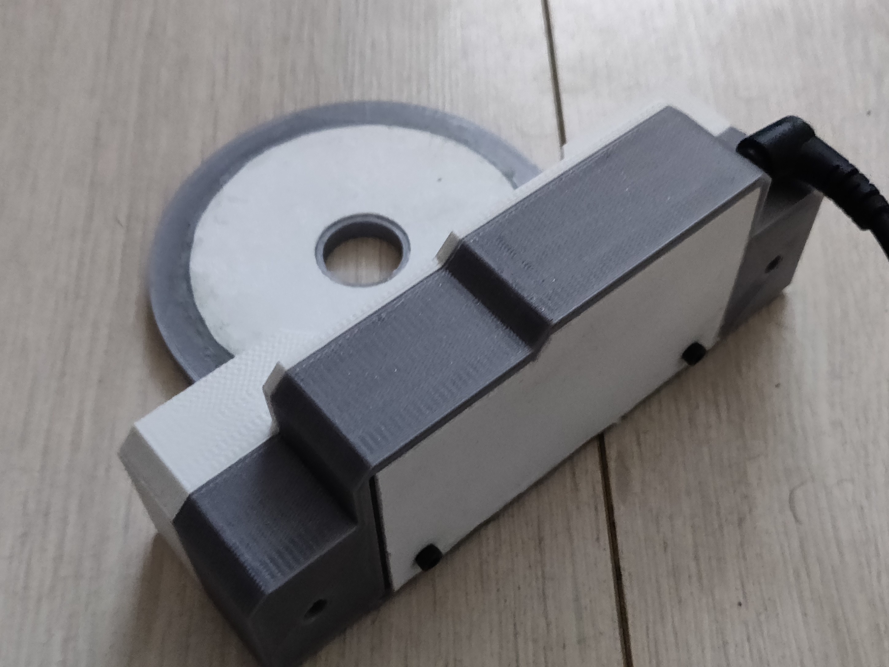
The receiver module consists of four parts, a base plate where everything is mounted, a cover for the receiver coil, a cover for the receiver board, and the receiver module itself. I did make a small design mistake though - I forgot about the tolerances when I decided to 3D print the base plate instead of laser cutting it. Because of this, the 3D printed parts did not perfectly fit together. So, I heavily relied on superglue and a hot glue gun to attach everything together. It is not pretty, but it works. The following picture the receiver module and resulting component.
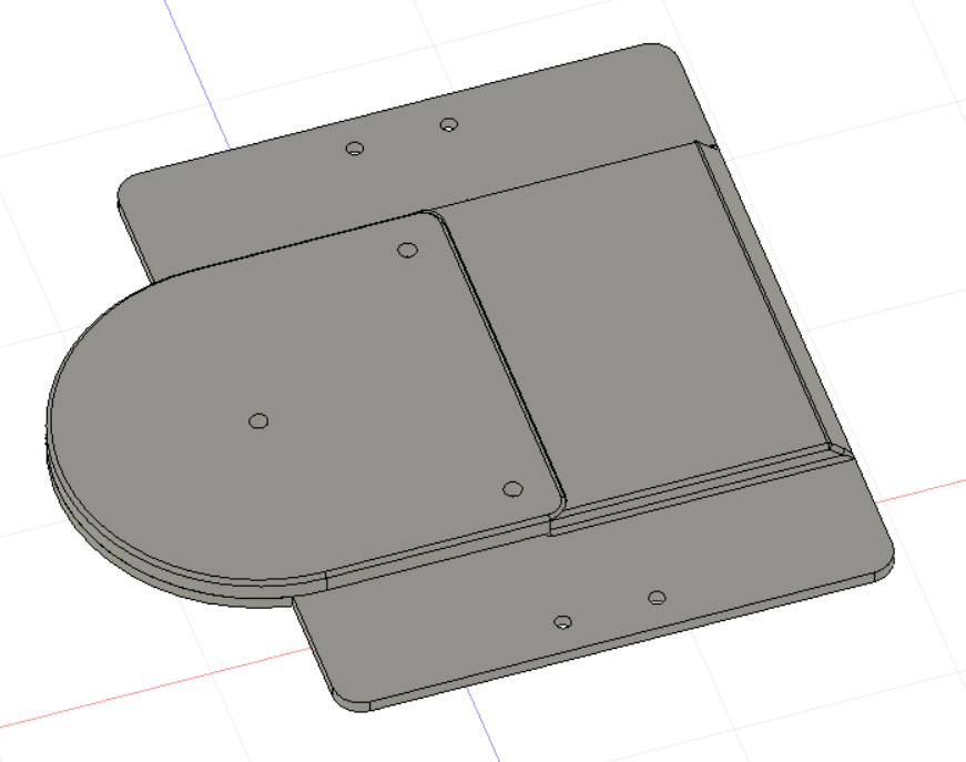
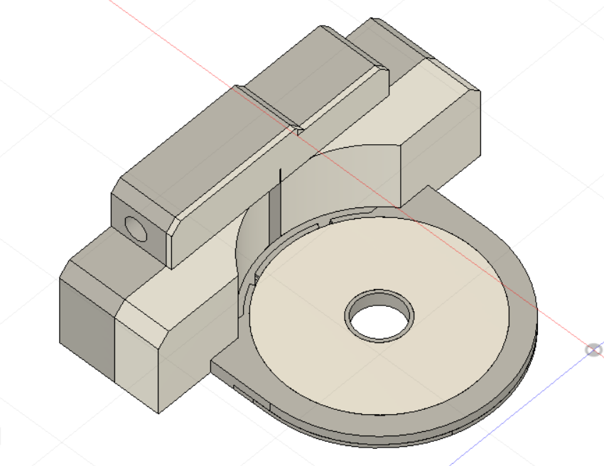
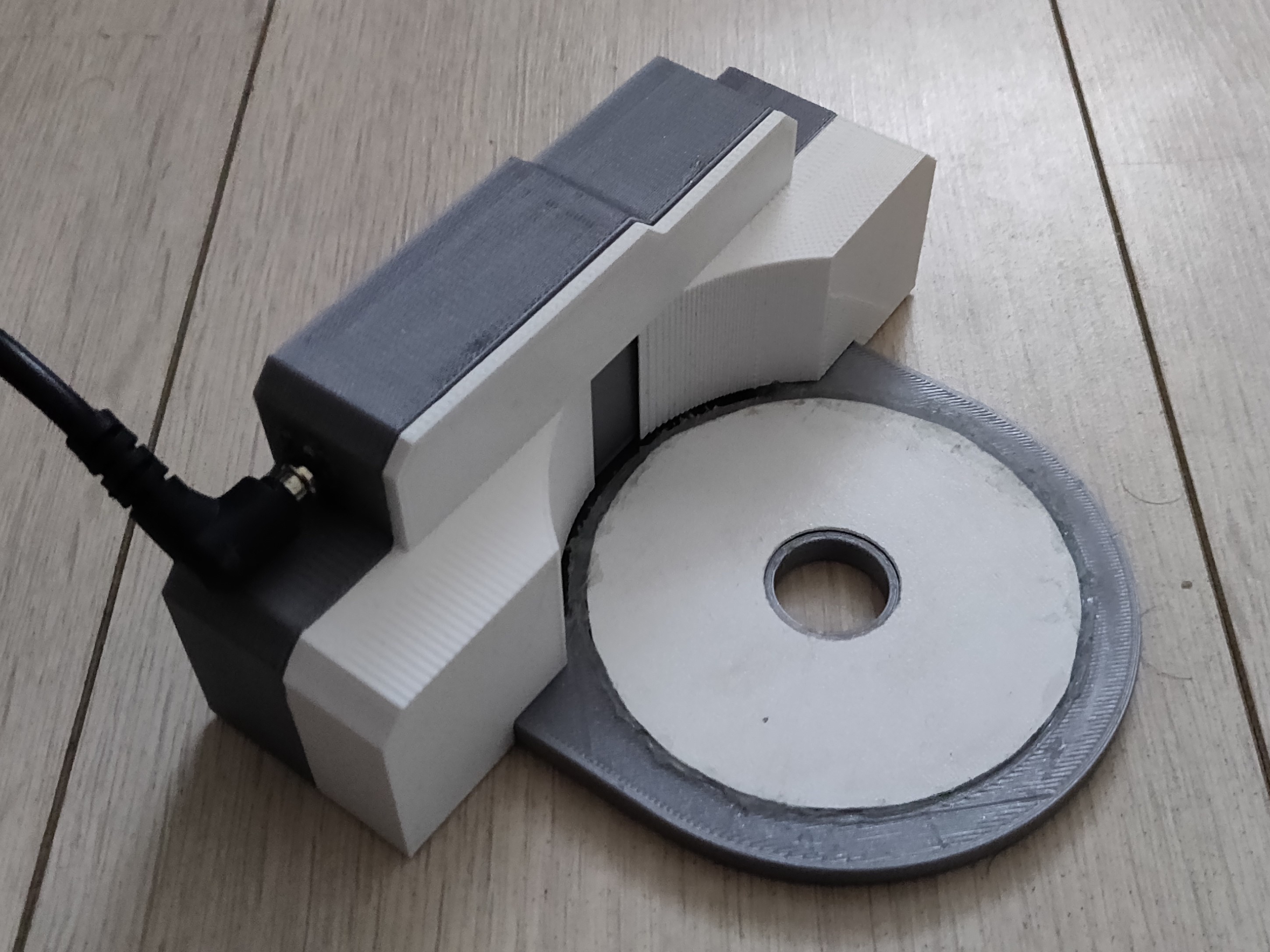
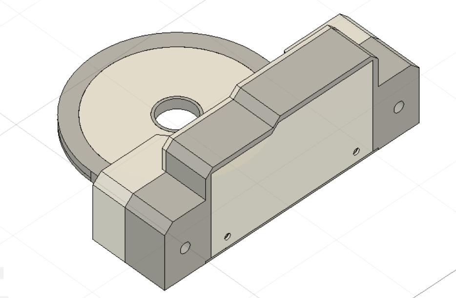
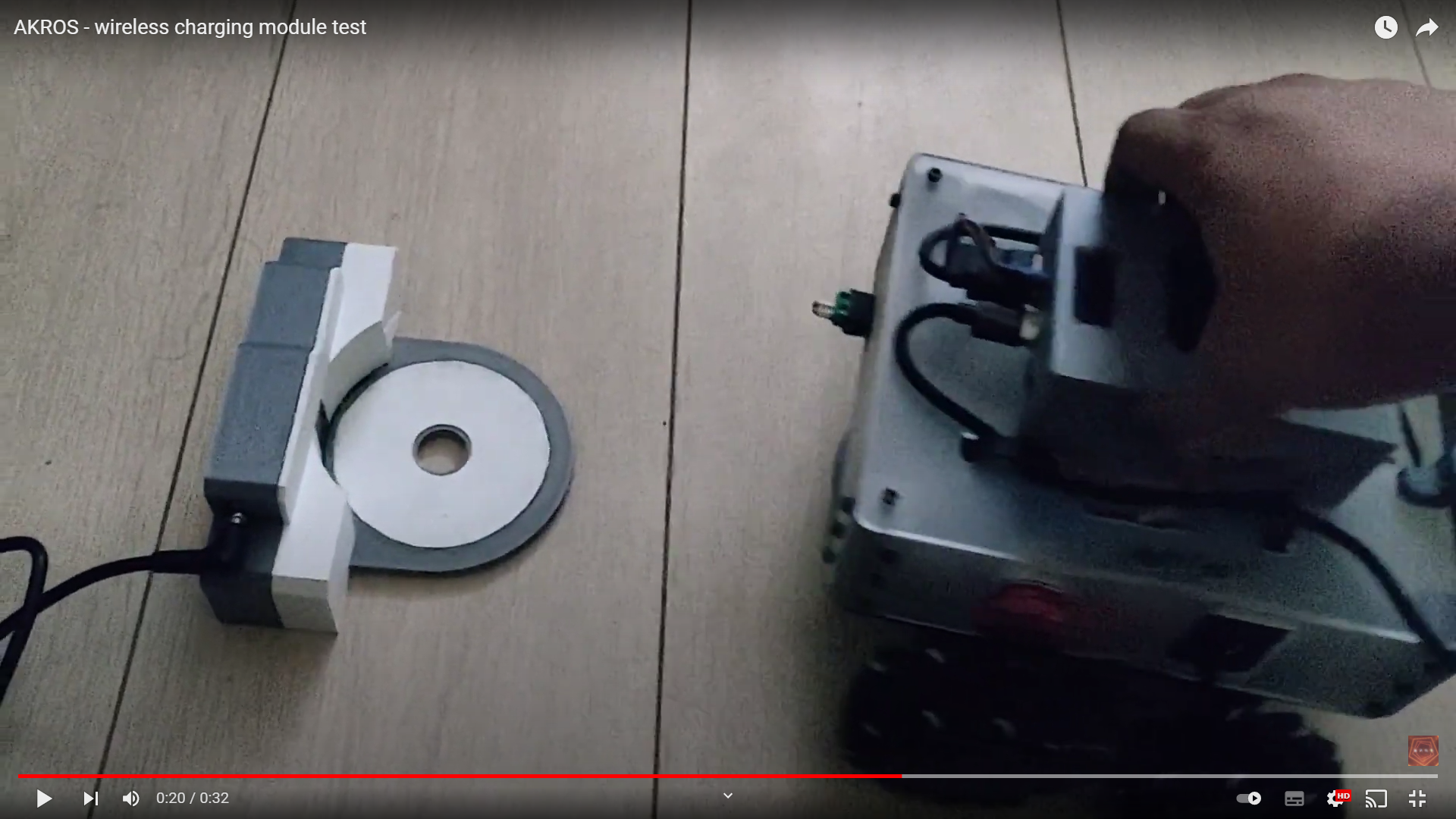
Next step was to update the transmitter design - to allow for the minor changes I had done in the receiver design. The transmitter consists of six parts - the base which holds the transmitter coil and board, a plate to cover the top of the coil, two parts that make up the transmitter board cover and back-plate, and a curved front part, in which the curved receiver base plate can fit. One thing I realized that the wireless charging continues to work (consistently at 12v), even if the two coils were at an offset of a few centimeters. So, I did not want the receiver to fit perfectly in the transmitter component, but rather be loosely fitting so that the robot can move in and out with ease and can still charge if the two coils are not perfectly aligned. For this reason, I increased the radius of the curve on the transmitter component. Once again, I made the mistake of forgetting about tolerances, so I had to file some parts down and stick the rest with blue so that everything fit together.
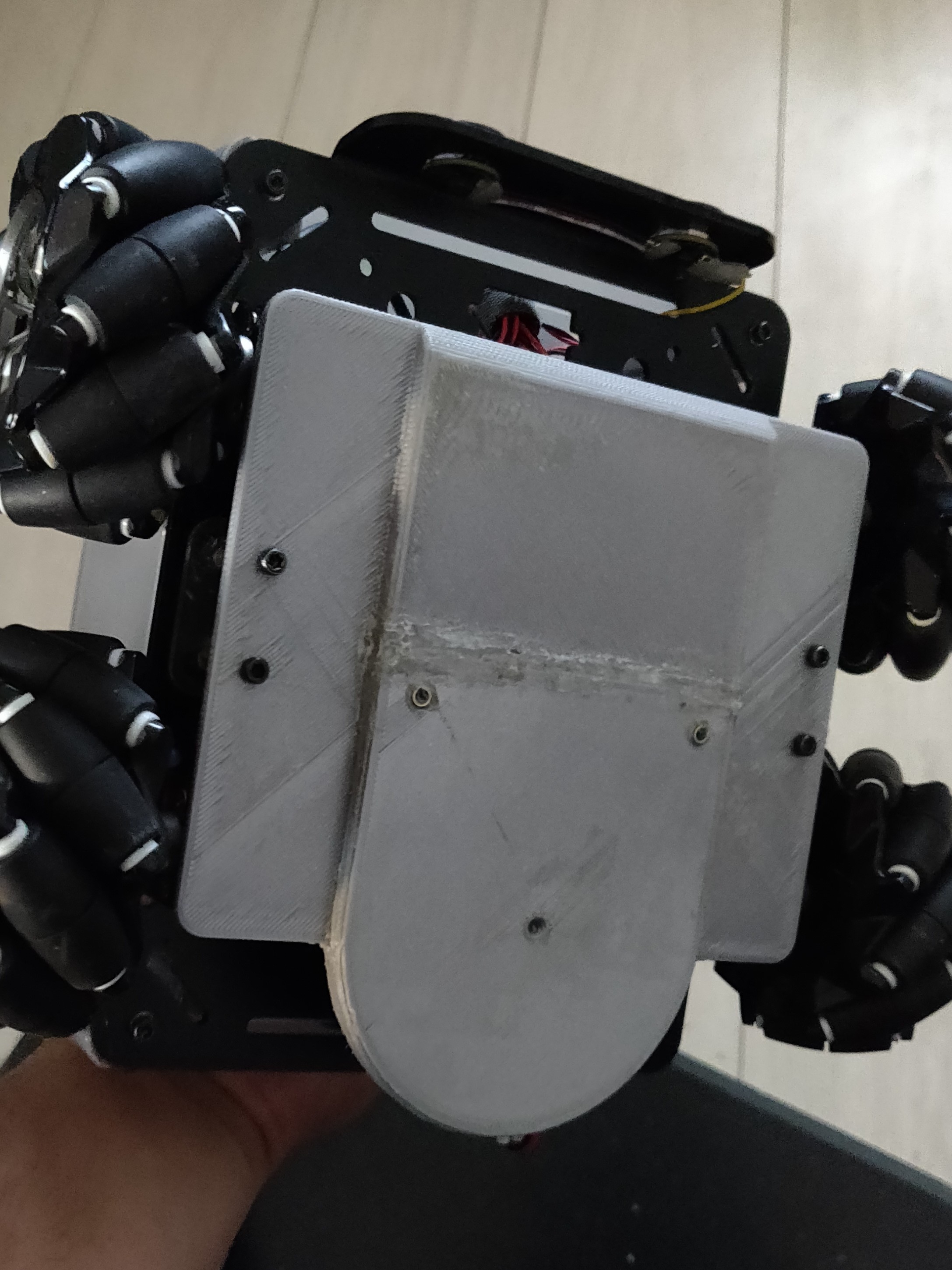
Here’s a video of the wireless charging module working individually and once its attached and wired to the robot. I attached the receiver module using four spacers to the bottom of the robot, and the transmitter module is placed on the floor (ideally against a wall). The transmitter module is attached to a 24V power adapter, and the receiver output is wired directly into the input power port of the in-board UPS.
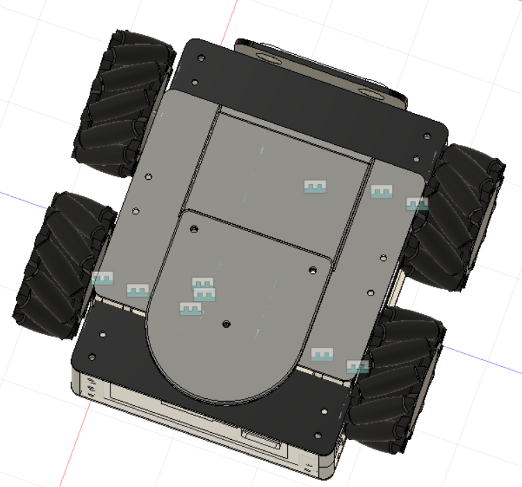
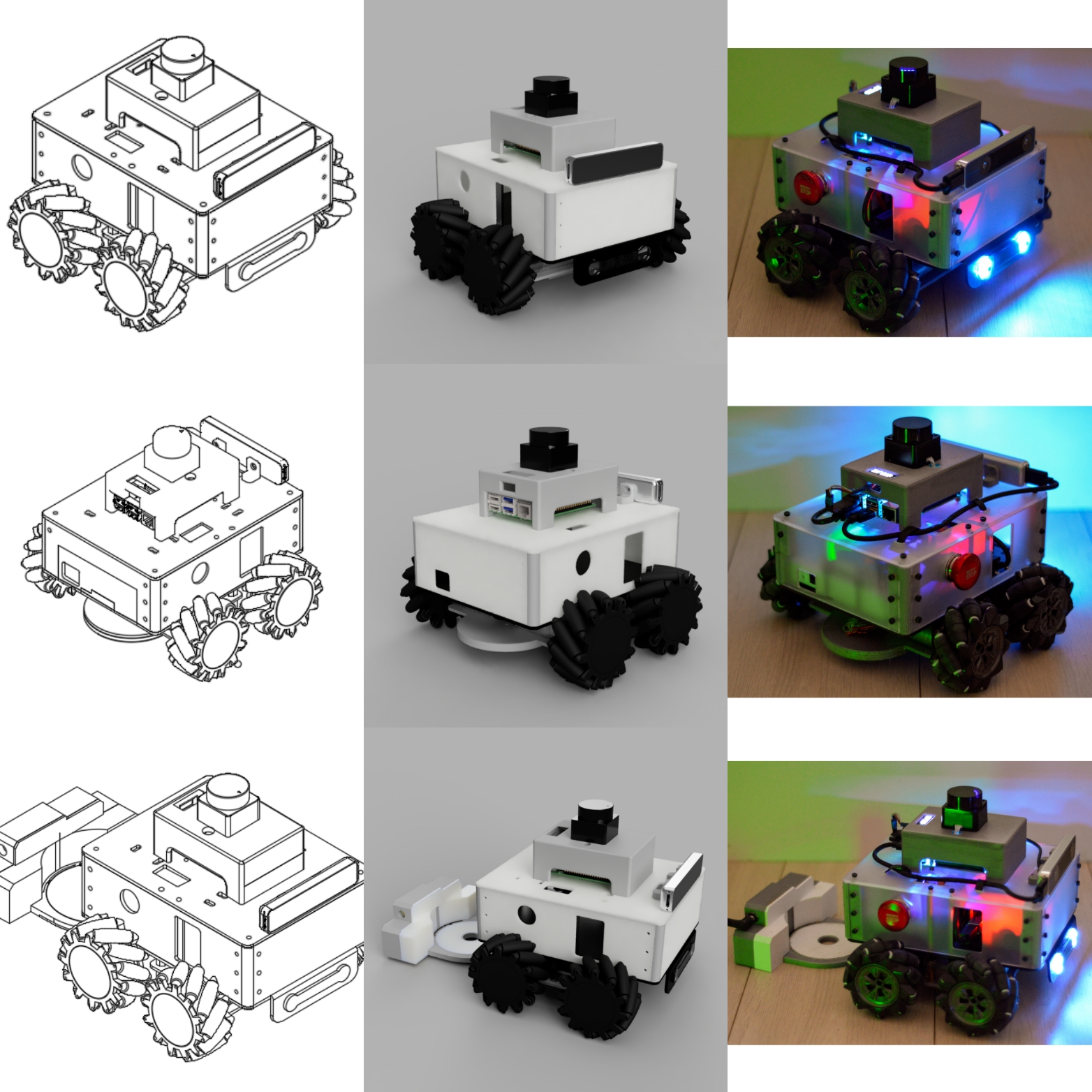
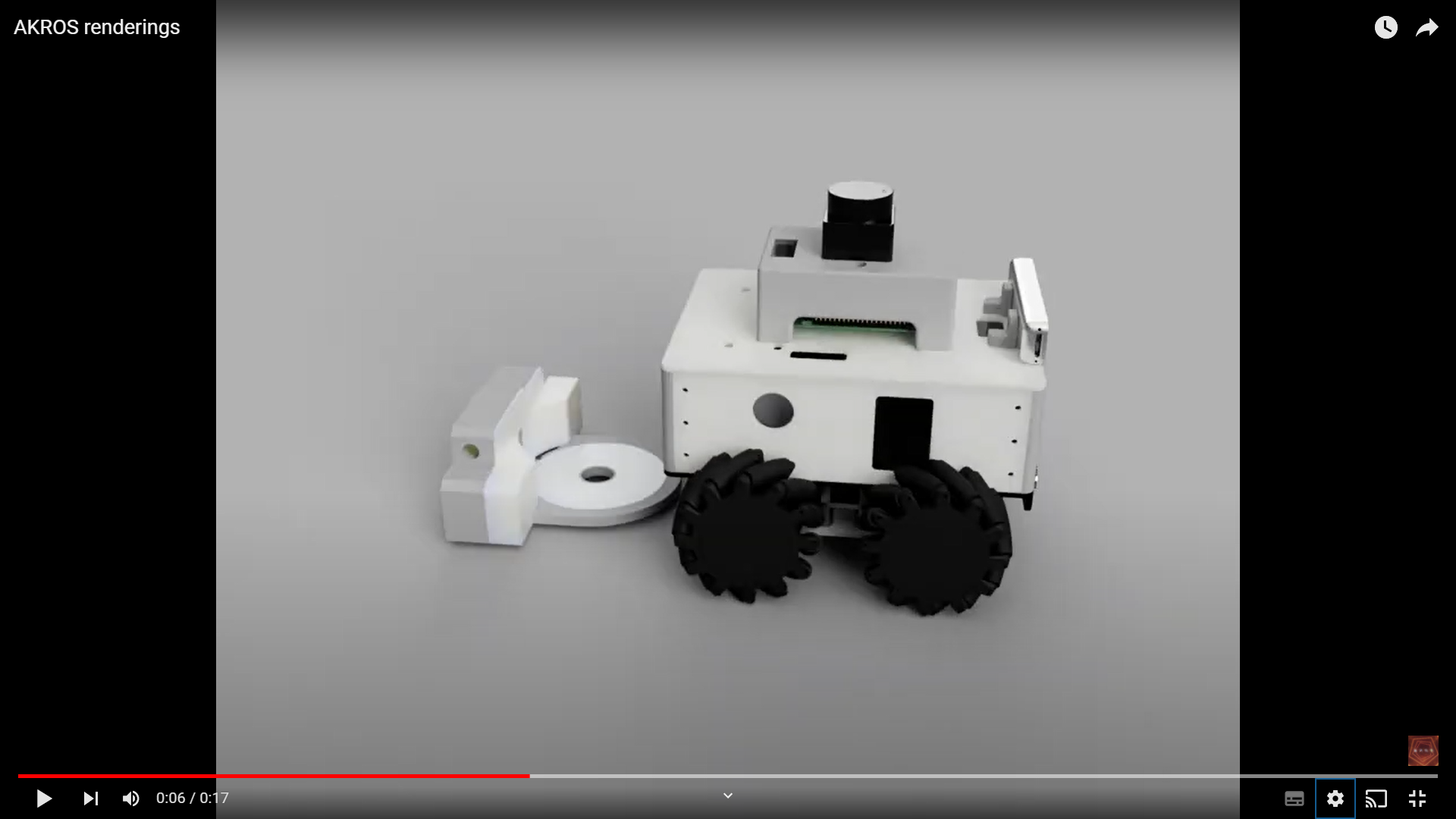
Finally, it was time to update my CAD model with parts, so that I can have an updated robot model for visualizations. This meant adding parts to my Fusion360 design like motors and encoders, which I found off the internet - these parts representative, they don’t look exactly like the parts on the robot - the mecanum wheel for example, has 9 rollers on the robot, but 12 in the 3D model. Some parts like the Arduino, motor driver, UPS/battery, wires and nuts/bolts are still missing, but in its current state, the CAD looks a lot like the real thing. Using Fusion360, I was also able to render the CAD design (which I then put them together in this really nice collage) and generate some videos:
That’s all for this week. For the next week, I plan on fine-tuning the odometry and the navigation stack, in order to optimize performance. I also have some minor issues with my behavior tree and high level sequences, so I plan on fixing them too. Next week, I’ll also receive a metal storage box that I ordered for AKROS and all its peripherals, and also some goodies for my next project. I’ll detail out my plans in the next blog post…