I’m finally back after quite a long, but well deserved hiatus from my side projects. Last time, before this long break, I finished up the mechanical parts of the robot, by adding a wireless charging module and by finishing the 3D model of the robot in Fusion 360. Now only one thing remained - the robot description file (or the URDF) so that I could visualize the state of the robot (using RViz or Foxglove Studio) during simulation (using Gazebo) or normal operation. During my break, I decided to hire a freelancer from Fiverr to help me with this bit, and within a week, I had the URDF file and sample launch files ready to review in my inbox. After a quick revision, the URDF of the robot was ready:
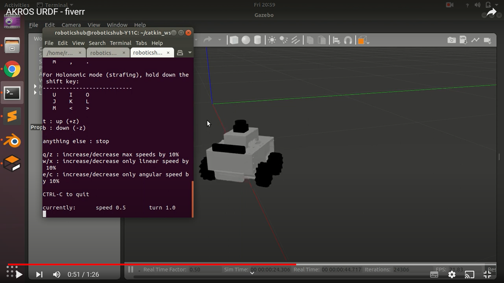
After updating the link and joints to match the AKROS software implementation, the URDF was ready to be used with the rest of the robot. It did work as expected on RViz, and while I did not test it, I also expect it to also work on Gazebo. However, I use Foxglove Studio for most of my development and testing, so it was important for me to be able to visualize the robot there. Unfortunately, loading the URDF on the URDF viewer and the 3D panel on Foxglove was trickier than expected. I started off with the Foxglove Studio documentation on the URDF viewer. This panel lets you load a URDF file and the 3D meshes from a local directory and visualize it on the side, separate from the 3D panel where the rest of the topics and TFs are visualized. Unfortunately in my case, I have the ROS nodes running on the Raspberry Pi on the robot, and Foxglove Studio running on my Windows laptop without a ROS installation. I first installed ROS on Ubuntu in Windows (WSL) and then implemented a multi-machine setup with the URDF package running on WSL and the rest of the packages running on the robot. However, while it almost worked once, I don’t know what I did, but it never worked again.
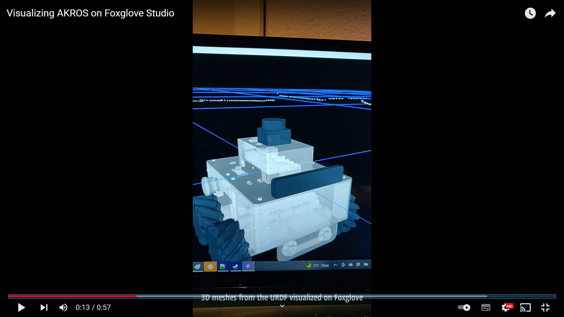
I had spent a couple of hours working on this, when I found an article on the Foxglove blog about visualizing ROS mesh markers where I realized that instead of loading the URDF, I could publish the URDF meshes as visualization_msgs/Marker messages, which could then be loaded on the 3D panel during a normal operation or even simulation. Since these markers are attached to their corresponding frames defined in the URDF, the frames would move according to the robot, which would move the meshes in the visualization. I immediately tried the sample code in their blog post. Since I had multiple meshes, I decided to publish them as an array (visualization_msgs/MarkerArray) instead, which worked without issues. I uploaded the STL files in a public GitHub repository, and during runtime these files are loaded by the mesh publisher and then published as a marker array.
Now the robot could be visualized in Foxglove during normal operation, but because the joint states are not being updated, the wheels could be seen moving in the 3D panel. So, in addition to a marker array publisher, I added a subscriber to the raw velocities published by the Arduino using wheel encoders. Using these subscribed velocities (linear x, linear y and angular z) and the robot geometries (wheel distances, wheel diameter), the position and velocity of each joint can be estimated and the joints can be rotated accordingly. The joint states are then published, which the robot state publisher uses to compute the forward kinematics and the corresponding TFs. I originally intended to use this alongside ros_control, which offers a general purpose control framework, but it seemed needlessly time-consuming to implement in comparison to my current custom solution. So, I did not go ahead with ros_control, but I will instead try ros2_control when I am porting to ROS2.
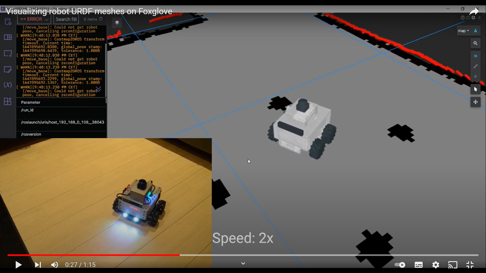
The final results of can be seen in the following two videos. The first videos shows the Foxglove visualization of the robot after the first step (marker array publisher), and the visualization after the joint states are also updated. The second video shows a side-by-side comparison of the robot’s actual motion and the visualization on Foxglove.
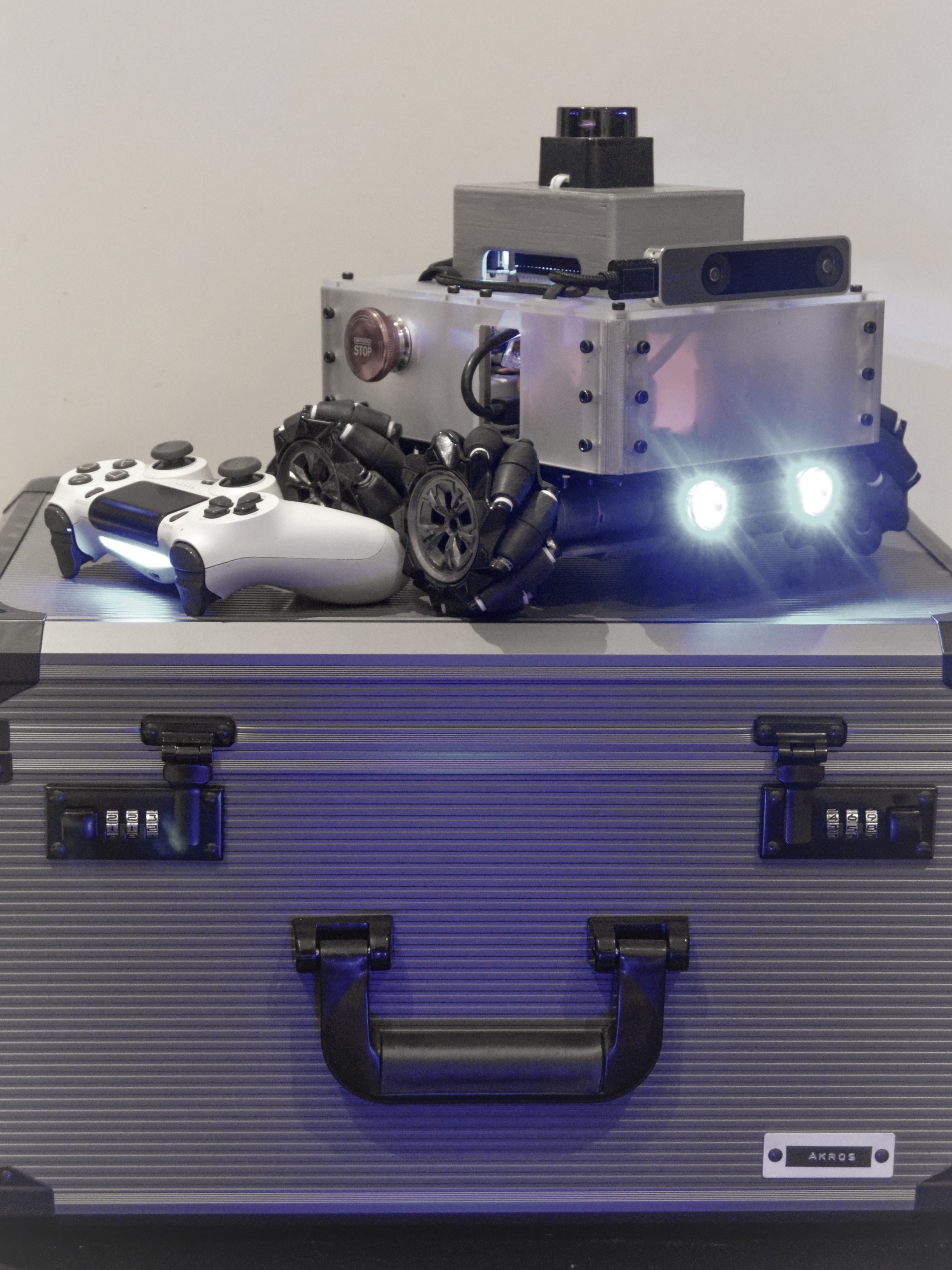
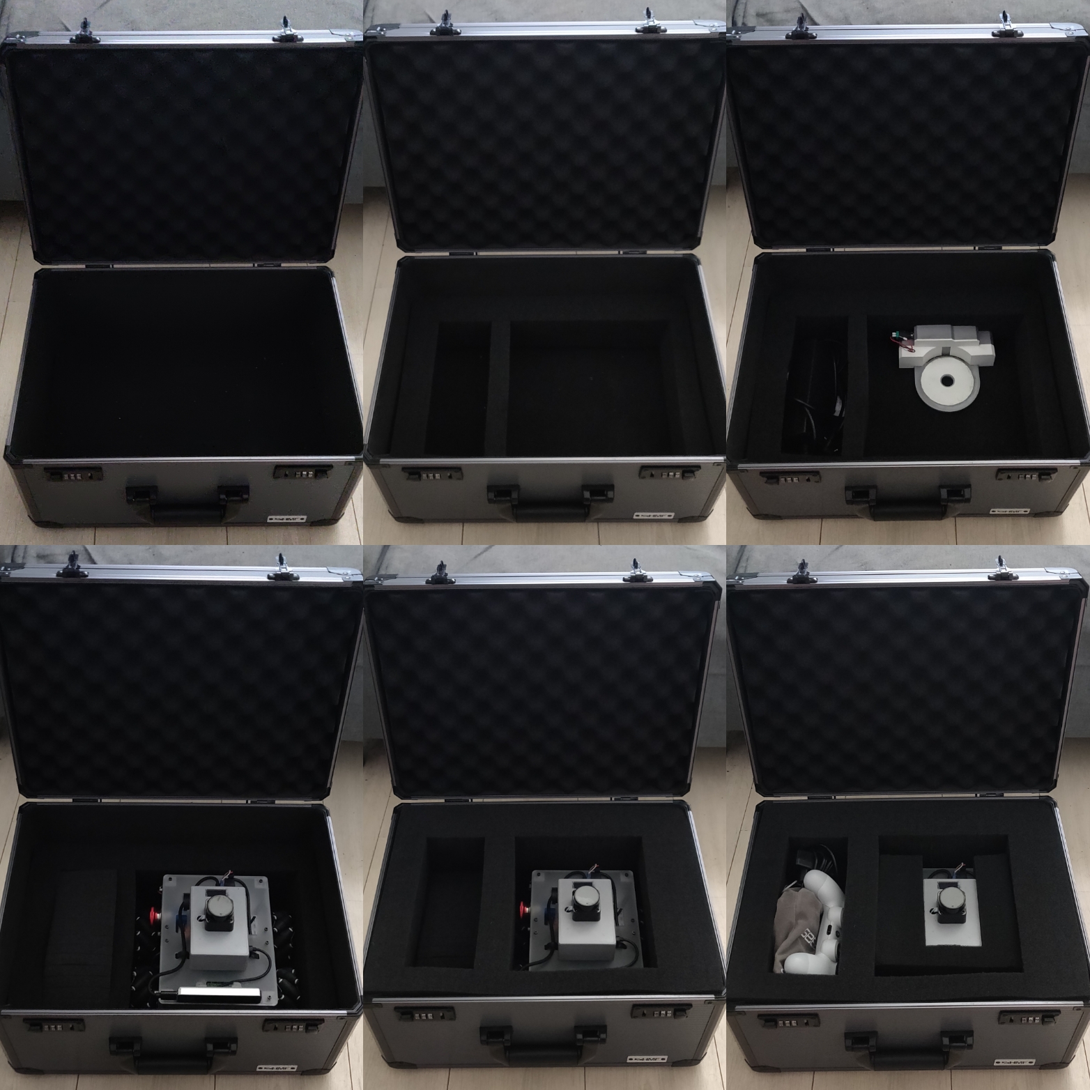
In addition to this, I also received a new carrying case for the robot, so now AKROS can travel in style, and without damage.
For my next steps with AKROS - the project almost coming to an end. A few things remain - a Gazebo simulation, fixing of some serial buffer/speed issues with the Arduino, and documentation. I haven’t worked with Gazebo for almost 5 years, and lots of things have changed, so it will take some time to get used to it. Since I’m lazy, I’ll probably leave that for later. I am planning on starting some documentation on the side, and I expect it to take a few months. In the meantime, I also want to focus on my next project - a Teensy 4.1 breakout board to prototype microROS applications. This board can also run ROSSerial when used with ROS1 and would be a natural alternative to the Arduino Mega onboard the robot. The Teensy’s much faster processor and communication methods such as Ethernet would certainly solve the issues with the Arduino Mega communication. Besides the AKROS upgrade, I also have other projects in mind for the Teensy board, both with and without ROS/microROS, and I will try and detail them in the following posts.