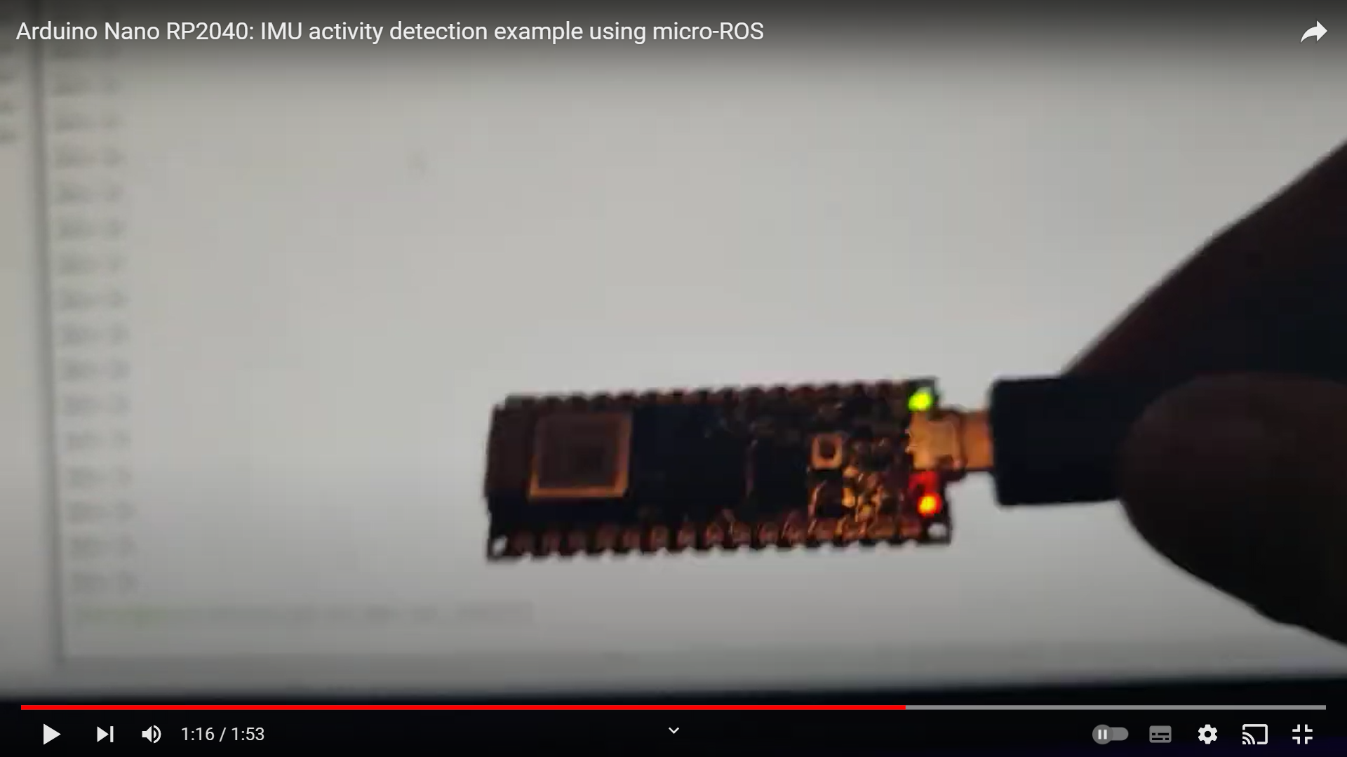
I spent some more time with the micro_ros_arduino examples throughout this week. I wanted to fix some of the issues from last week and also explore the use of UDP over Ethernet, with a Teensy 4.1 and an Arduino Portenta H7 Lite Connected. I started off by re-running some of the examples from last week. First, the IMU ML example for the Arduino Nano RP2040 Connect. This example is supposed to publish two messages - one with the detected activity and one with the number of steps, and it works very well with the serial transport. However, last week, I was unable to see any published topics when I tried the same example using UDP over WiFi. I concluded that it could be because of the Nano RP2040’s memory limitations, and also that it needed further investigation. Turns out is was just a silly error on my part. I made a typo with the port number on the Arduino IDE. I fixed it, and it works as expected, here’s a video:
Next, the Time Sync example - I wasn’t able to test this with the serial transport as I did not have a GUI development environment and was not able to stream serial data on the terminal. However, with WiFi, I could connect to the micro-ROS agent wirelessly, which meant I could connect the device to the Arduino Serial Monitor running on my Windows laptop and read the serial data. This was tested during the week and it worked as expected for the Nano RP2040. There’s a video later in this post showing the example working with the Portenta with UDP over Ethernet. It also worked as expected with WiFi on the Portenta, but only after a couple of attempts as I had connection issues again. The connection dropouts significantly reduced after I increased the timeout period for the synchronization.
Arduino Portenta H7 (UDP over Ethernet Transport)
Previously, with the Portenta H7, I implemented the serial and udp4 (over WiFi) transports. Both of these were configured using a single line in the setup function in Arduino: set_microros_transports(); and set_microros_wifi_transports("SSID", "PASSWORD", "micro-ROS Agent (WLAN) IP", 8888) for the Serial and WiFi transports respectively. For UDP over Ethernet, first you need the Portenta Breakout Board which has a RJ45 Ethernet connector. Once the hardware setup is ready, it is setup to communicate over micro-ROS like this (on the Arduino IDE):
byte arduino_mac[] = {0x01, 0xAB, 0x23, 0xCD, 0x45, 0xEF};
IPAddress arduino_ip(192, 168, 1, 109);
IPAddress agent_ip(192, 168, 1, 100);
set_microros_native_ethernet_udp_transports(arduino_mac, arduino_ip, agent_ip, 8888);
On my first try, this did not work because there was no IP set for the eth0 network on my Raspberry Pi. I fixed it using this tutorial by Ubuntu. I had to set a static IP for eth0 by changing the existing .yaml file in /etc/netplan on my Raspberry Pi 4. I had already updated this file while setting up my Raspberry Pi WiFi. My new .yaml file looks like this:
network:
    ethernets:
        eth0:
            addresses:
                -192.168.1.100/24
            gateway: 192.168.1.1
            nameservers:
                addresses: [8.8.8.8, 8.8.4.4]
            optional: true
    wifis:
        wlan0
            dhcp: true
            access-points:
                "SSID:
                    password: "PASSWORD"
    version: 2
Now, when an Ethernet device is connected to the Raspberry Pi, the eth0 interface is loaded with the IP address 192.168.1.100 with 192.168.1.1 as a gateway. This can connect to the internet using Google’s public DNS servers (8.8.8.8 and 8.8.4.4). Now this is set up, the following command can be used to connect to the micro-ROS device with UDP over Ethernet:
$ ros2 run micro_ros_agent micro_ros_agent udp4 --port 8888
At first, I struggled to get these steps working, mainly because I was focusing on finding the MAC address of the Arduino Portenta, and also its IP address. I checked the Arduino forums, but at first I saw comments that said that the MAC address is usually printed on the box the Portenta came in. I had thrown that away long ago, so I was stuck. Fortunately, I came across the correct answer that said that I could choose the MAC address randomly, as long as its not identical to any other device its connected to. The second issue was the IP address, which again, needs to be assigned by the user, as long as it does not conflict with any other device. Finally, the agent_ip is the IP address of the micro-ROS agent(on eth0) which, as defined in the netplan configuration is 192.168.1.100. The port number, defined above as 8888 can also be changed. Once I figured these things, I was able to get the examples working.
I tried all the Portenta examples from the last two updates with Ethernet and most worked as expected. The only problem was the Reconnection example. Unlike with WiFi where the connection kept dropping off, with Ethernet the issue was from the code - while the connection remained stable, the code for some reason was unable to ping the micro-ROS agent. The following snippet should explain things better:
  switch (state) {
    case WAITING_AGENT:
      EXECUTE_EVERY_N_MS(500, state = (RMW_RET_OK == rmw_uros_ping_agent(100, 1)) ? AGENT_AVAILABLE : WAITING_AGENT;);
      break;
    case AGENT_AVAILABLE:
      state = (true == create_entities()) ? AGENT_CONNECTED : WAITING_AGENT;
      if (state == WAITING_AGENT) {
        destroy_entities();
      };
      break;
    case AGENT_CONNECTED:
      EXECUTE_EVERY_N_MS(200, state = (RMW_RET_OK == rmw_uros_ping_agent(100, 1)) ? AGENT_CONNECTED : AGENT_DISCONNECTED;);
      if (state == AGENT_CONNECTED) {
        rclc_executor_spin_some(&executor, RCL_MS_TO_NS(100));
      }
      break;
    case AGENT_DISCONNECTED:
      destroy_entities();
      state = WAITING_AGENT;
      break;
    default:
      break;
  }
When the agent is connected (AGENT_CONNECTED), the code executes a check every 200 ms to see if the agent is still connected. If the check, done using the rmw_uros_ping_agent(100, 1) function from the micro-ROS API returns False, then the state is set to AGENT_DISCONNECTED, where all created entities are destroyed and the state is set to WAITING_AGENT. The WAITING_AGENT state remains till the same rmw_uros_ping_agent(100, 1) function can be used (every 500 ms) to check if the agent is available and the state is set to AGENT_AVAILABLE. Here the entities are created again and the state is set to AGENT_CONNECTED, where once again the rmw_uros_ping_agent(100, 1) function returns false and the loop continues. This causes the entities to be created and destroyed in a loop over and over again. I haven’t been able to resolve this issue. I would have liked to test it out with Teensy 4.1 to see if I can reproduce it, but there were some issues as I’ve explained later. The WiFi example still works, but once again with connection dropouts. All I can say about it is this.
To summarize, the UDP over Ethernet transport works to an extent on the Arduino Portenta using the micro_ros_arduino pre-compiled libraries. I am able to do basic ROS stuff like publishing/subscribing to different types of messages and implementing service servers and clients. Here’s an example of the Time Sync example working over Ethernet:
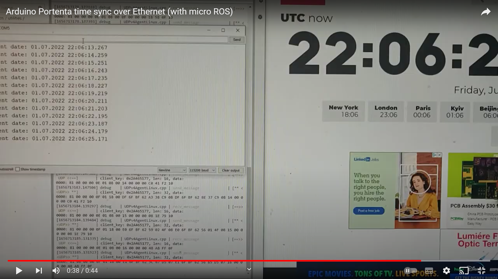
In the above video, the rmw_uros_sync_session(timeout_ms) function from the micro-ROS RMW API is used to sync the time between the micro-ROS agent and the micro-ROS client. As the video shows, the sync is quite accurate and functions without any timeouts. This also did not happen over WiFi with the Nano RP2040, but there were some dropped connections when working with the Portenta as explained earlier. Also in the video, the time on my laptop is two hours ahead of the synced time because my laptop shows the time in CEST, while the synced time is based on UTC.
Teensy 4.1 (Serial Transport)
Next, I set the Portenta aside and started with a Teensy 4.1 Setting up the Teensy takes a few extra steps but these are only done once when setting up the environment. My first step was to install Teensyduino and configure it in the Arduino IDE. I already had Teensyduino installed but I have been using it with PlatformIO. So, everything was already configured but here’s the tutorial anyway. Next, I needed to patch the Teensyduino installation to use the pre-compiled micro-ROS libraries by replacing platform.txt (in [Arduino installation path]/hardware/teensy/avr/) with this platform.txt. I then used this tutorial to configure the Teensy on the ROS2 host and to run the micro-ROS agent. I did not have to do most of the things in the tutorial since I am using Windows 10 with Arduino IDE and pre-compiled libraries, so you can scroll down to the section that talks about setting up the udev rules and then to the section about running the micro-ROS agent.
Once the Teensy 4.1 was set up, I simply connected it via USB to the Raspberry Pi 4 on the AKROS robot and tried out all the examples from the Portenta experiments. All the examples worked as expected using the serial transport. I could already use the serial transport with 2 subscribers and 2 publishers, which is already much better than the Arduino Mega with ROSSerial. Looks like I don’t need Ethernet after all, although I will still experiment with it.
Teensy 4.1 (UDP over Ethernet Transport)
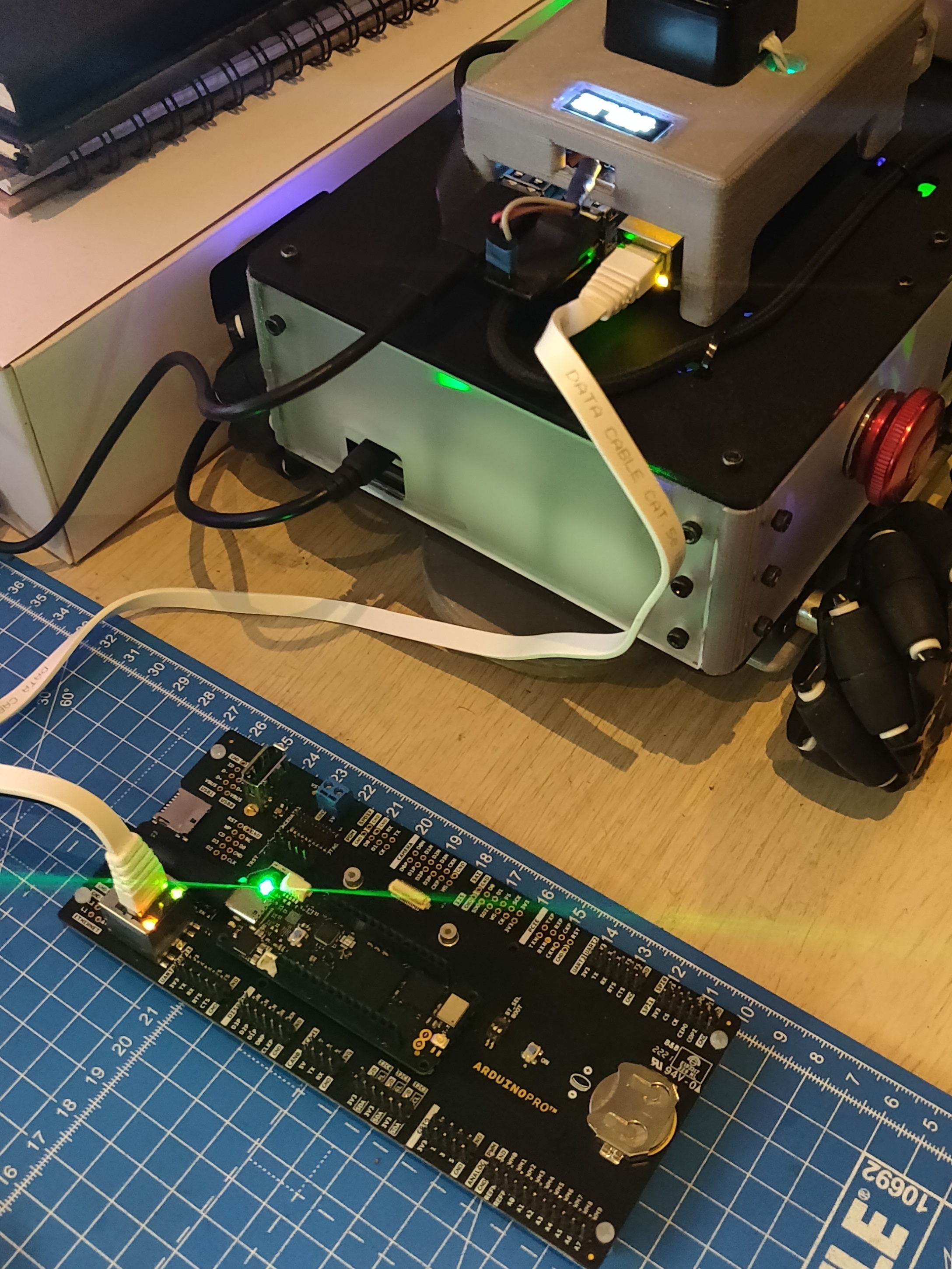
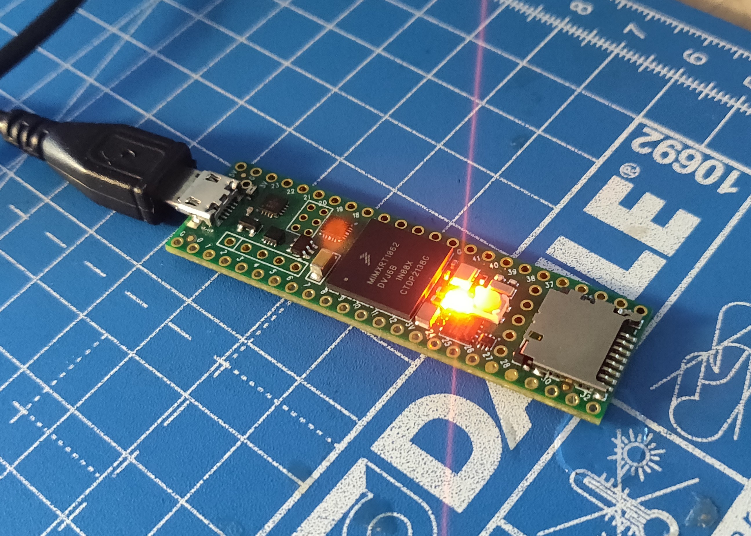
Like the Portenta H7, the Teensy 4.1 needs an external breakout board for its Ethernet connector. In my case, I have two Teensy 4.1 boards with two separate breakout boards for the Ethernet connector - the first is a handy Ethernet Kit sold by PJRC (the makers of the Teensy). This is simply a breakout board with a solder-it-yourself RJ45 Ethernet connector and a ribbon cable that connects to the exposed pinouts on the Teensy 4.1. The second option I have is the Teensy 4.1 Expansion Board from BurgessWorld which I purchased from Tindie. It is an Arduino Mega form-factor expansion board that incorporates PJRC’s Ethernet Kit on-board, along with a few more features. This board has already been assembled and wired to the AKROS robot as a replacement to the Arduino Mega in a previous post. Unfortunately, the Ethernet connector on the expansion board is not wired internally to the Teensy’s Ethernet pins, but needs the same ribbon cable as the Ethernet Kit. This means, I need to open up the robot, remove the motor drivers which block access to the Ethernet pins, wire the Ethernet connector and then re-assemble. So, I decided to try it with my spare Teensy and the Ethernet kit instead.
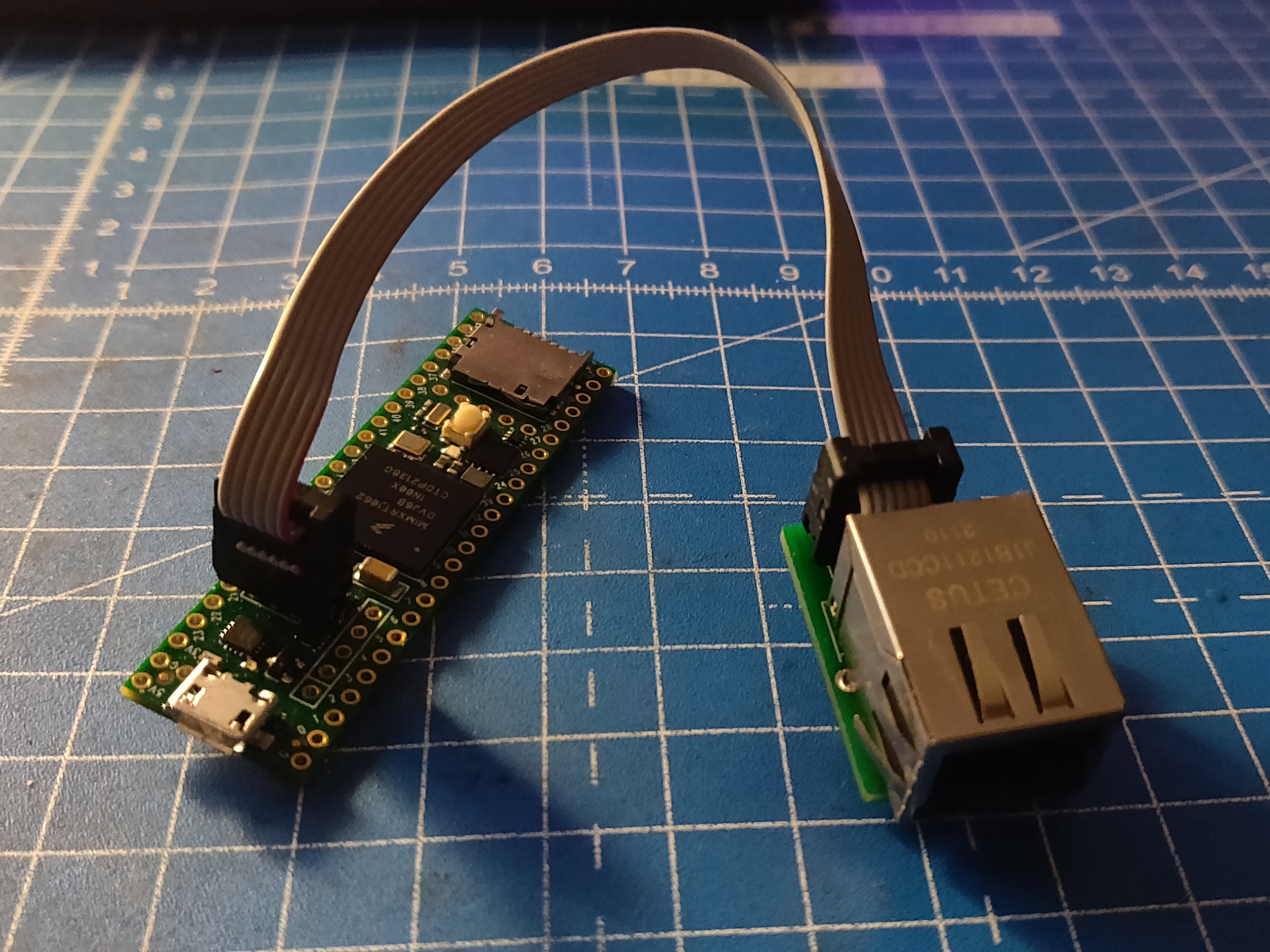
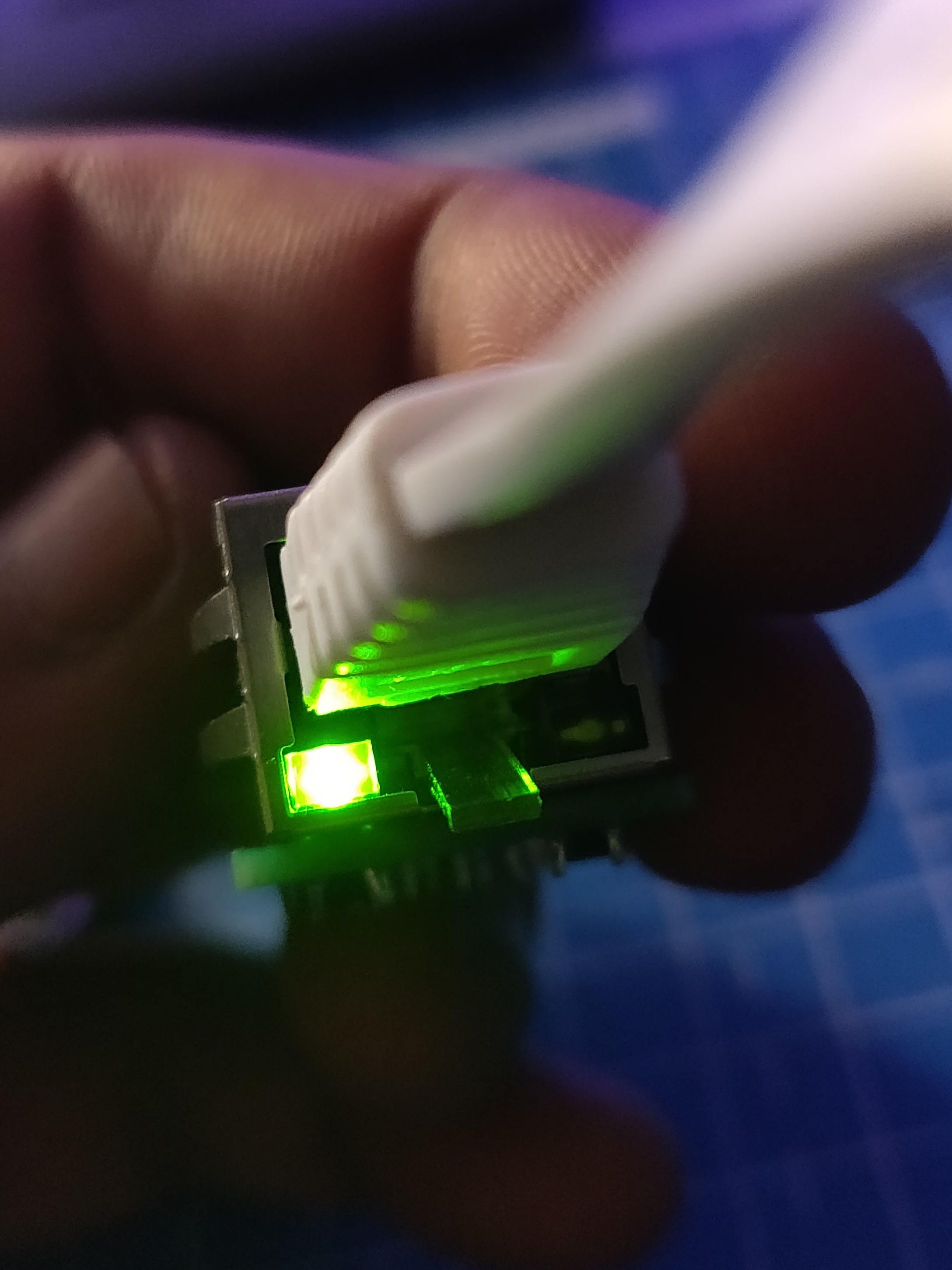
I followed the same procedure as with the Portenta. I assigned a MAC and IP address to the device and successfully uploaded the code from the Arduino IDE. Next, I connected the Ethernet kit to the Teensy and the Raspberry Pi. The LEDs on the Ethernet connector on the Rasperry Pi turned on and I was able to validate that a static IP has been assigned to eth0. Despite this, the Teensy does seem to connect to the Raspberry Pi. On the Ethernet kit, only the green light LED turns on but the orange one doesn’t. Eventually the micro-ROS code times out and enters the error loop. At first I thought this was an issue with the Ethernet kit, so I double checked the soldering and the wiring and found nothing wrong. I also checked the same code on the expansion board and observed the same issue. I need to investigate this further as I’m not sure if its something I’m doing wrong, or if it is something in the pre-compiled librares. Either way, the example Ethernet Publisher code on the micro_ros_arduino repo is meant for both the Arduino Portenta and the Teensy 4.1, but for me, it only works on the Arduino Portenta. Its a bummer that so far there doesn’t seem to be any online documentation, tutorial or working example about implementing Ethernet communication with micro-ROS, especially using the Teensy 4.1.
Raspberry Pi Pico W
In other news, the Raspberry Pi Foundation launched the Pico W, after teasing this image of a Pi Cow a day earlier and then this video with a banana. It did make me feel stupid for a while, for buying an Arduino Nano RP2040, which costed 4 times the price of a Pico W ($6). but after reading a bit more about the Pico W (and also the Nano RP2040), I realized that the cost of the Nano is justified - it comes with 8x the flash (Pico W comes with 2MB QSPI Flash, while the Nano RP2040 has 16MB), a 6-axis IMU (with a ML core, motion/activity detection and an embedded temperature sensor), an onboard MEMS microphone, and the Nano RP2040 is also much smaller than the Pico or the Pico W. Also, unlike the ESP32, Arduino is just as reliable as Raspberry Pi in terms of community, support and documentation, so I am in safe hands here. So for now, I am going to stick with the Arduino Nano RP2040 for my very first PCB design. Once I get more confident designing and assembling PCBs (especially with SMD components), I would try using the RP2040 chip directly, and make my own Pico W board. Alongside the Pico W, the RPi Foundation also launched the Pico H (for $5) which is a Pico with a 3 pin debug connector, and will be launching the Pico WH (for $7) later this year. These devices are all the same size and share a standard GPIO layout.

Meanwhile Pimoroni also launched a literal butt-load of Pico and Pico W products on their websites. It’s definitely created a lot of buzz on Twitter. While these new products are really tempting, they are also quite expensive. Also, I already have a quite a few projects in progresss and I dont want to pile on more stuff. I will still get the Pico W just to play around with micro-ROS and compare it with the Nano RP2040, but they’re already out of stock in the Netherlands, so I have to wait till my local stores restock it.
Next Steps
I’ve been wanting to get some 3D prints for the last two weeks, for the new micro-ROS based mecanum wheel robot I’m building. I did get time to visit the office, but since the last week the designs are being updated, so the 3D prints will have to wait for a while. I’m also considering the next version of AKROS with ROS2, and thinking of changing the navigation module yet again to make the entire system more compact. I might have found a way, but this means more 3D printing and probably some more laser cutting as well. If I can get the navigation module compact enough, I could then add another level on top to carry extra payload.
As for the next few weeks, I want to finish up these ROS examples - First I want to get UDP over Ethernet working with the Teensy 4.1. Then, like I mentioned last time, I want to experiment with multiserial configurations on micro-ROS and follow some advanced tutorials like tracing and creating custom messages/transports. I also want to delve a bit deeper into the micro-ROS fundamental concepts, architecure and API. This will probably me my final two weeks experimenting with micro-ROS examples and tutorials. Next, I want to focus all my time on designing the Nano RP2040 motor controller schematic and layout on KiCAD. I’m also expecting (with fingers crossed) some more packages that I ordered over the last two months that were stuck in transit for a very long time. Hopefully they arrive and I can share some pictures in the next update…