Turns out I’m much more productive on long weekends, so here’s another post. A few months ago, while looking for some components online, I found the micro:Maqueen Mechanic Loader module. It’s a neat little metallic loader module powered by a metal servo motor. I thought it would be perfect for the Jetbot2 and the Easter weekend was the perfect opportunity to assemble and test it out.
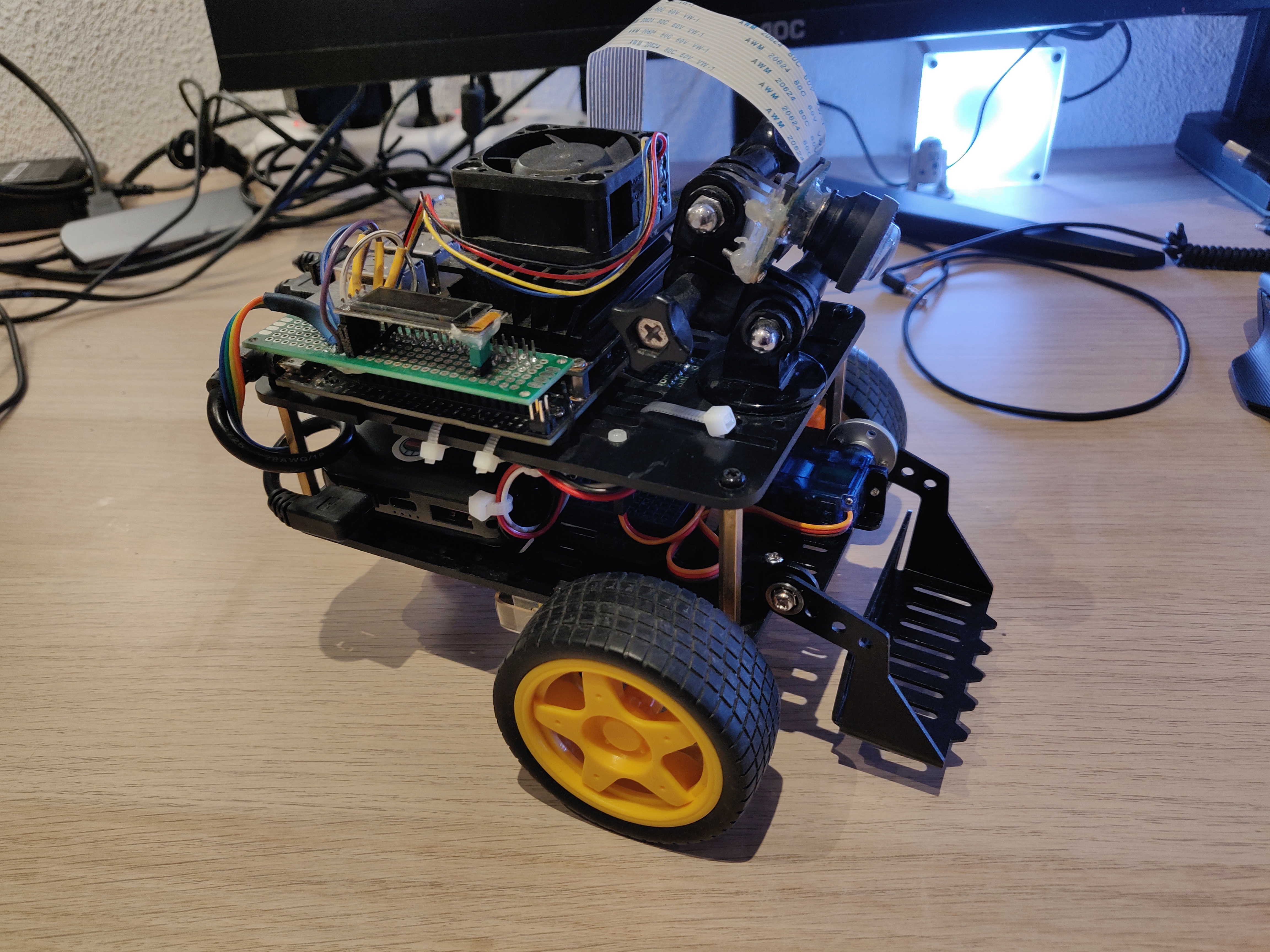
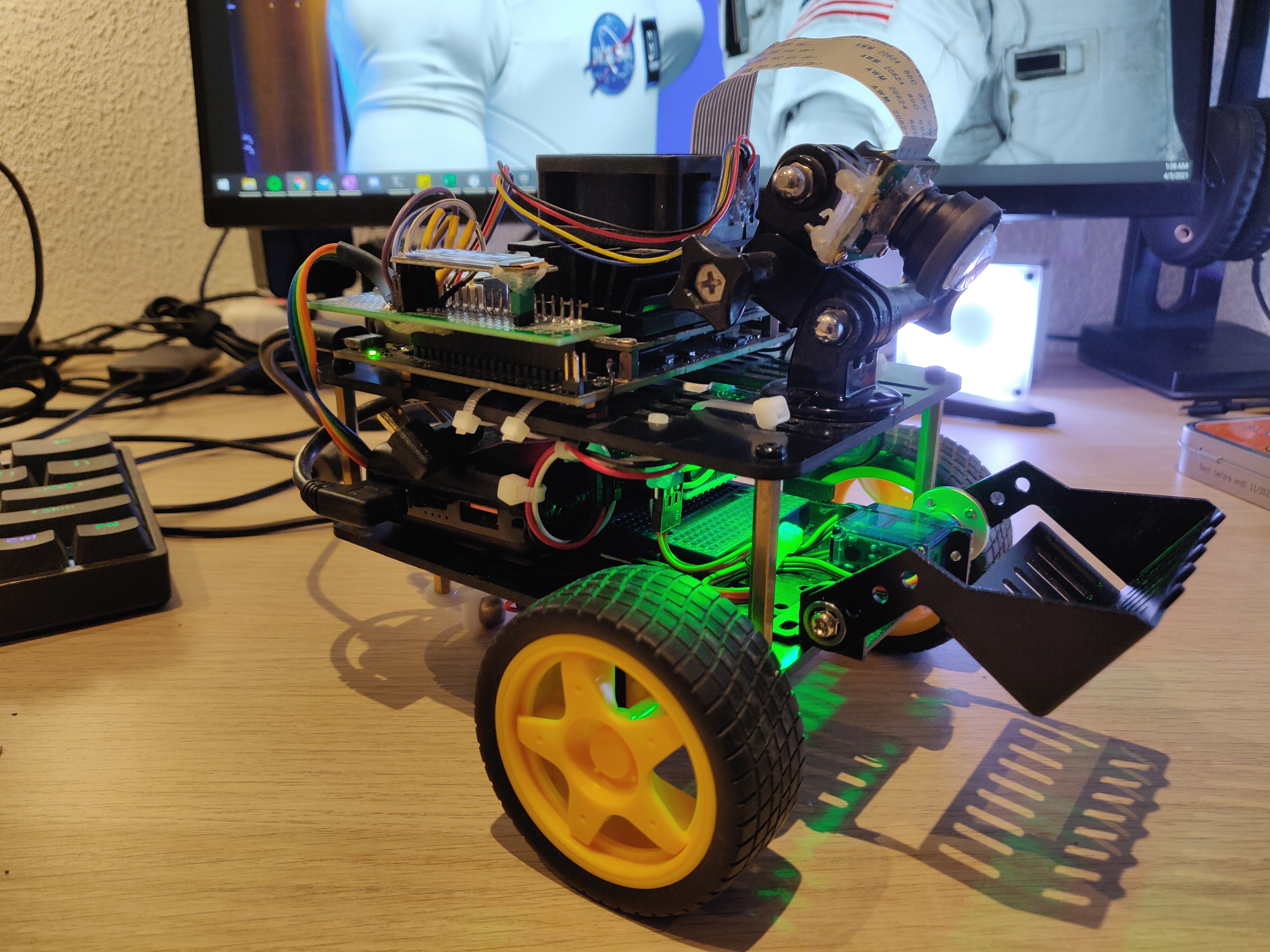
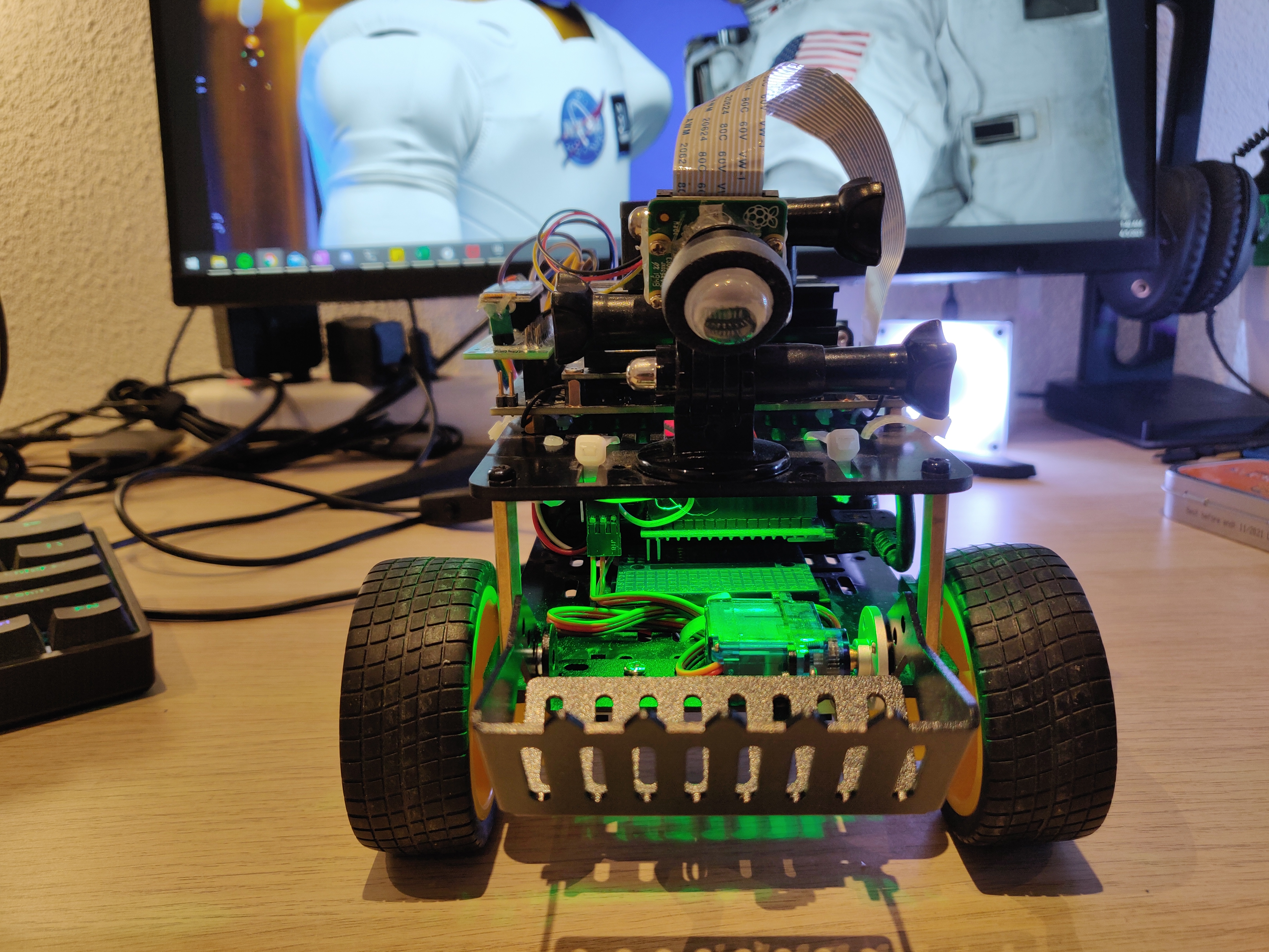
Fortunately, the bottom plate of the Jetbot2 has some spare holes which match up exactly with the loader’s mounting points. Its not entirely centered though, but the offset is quite small (~1cm) and not really a big deal (for me). The assembled robot looks like this:
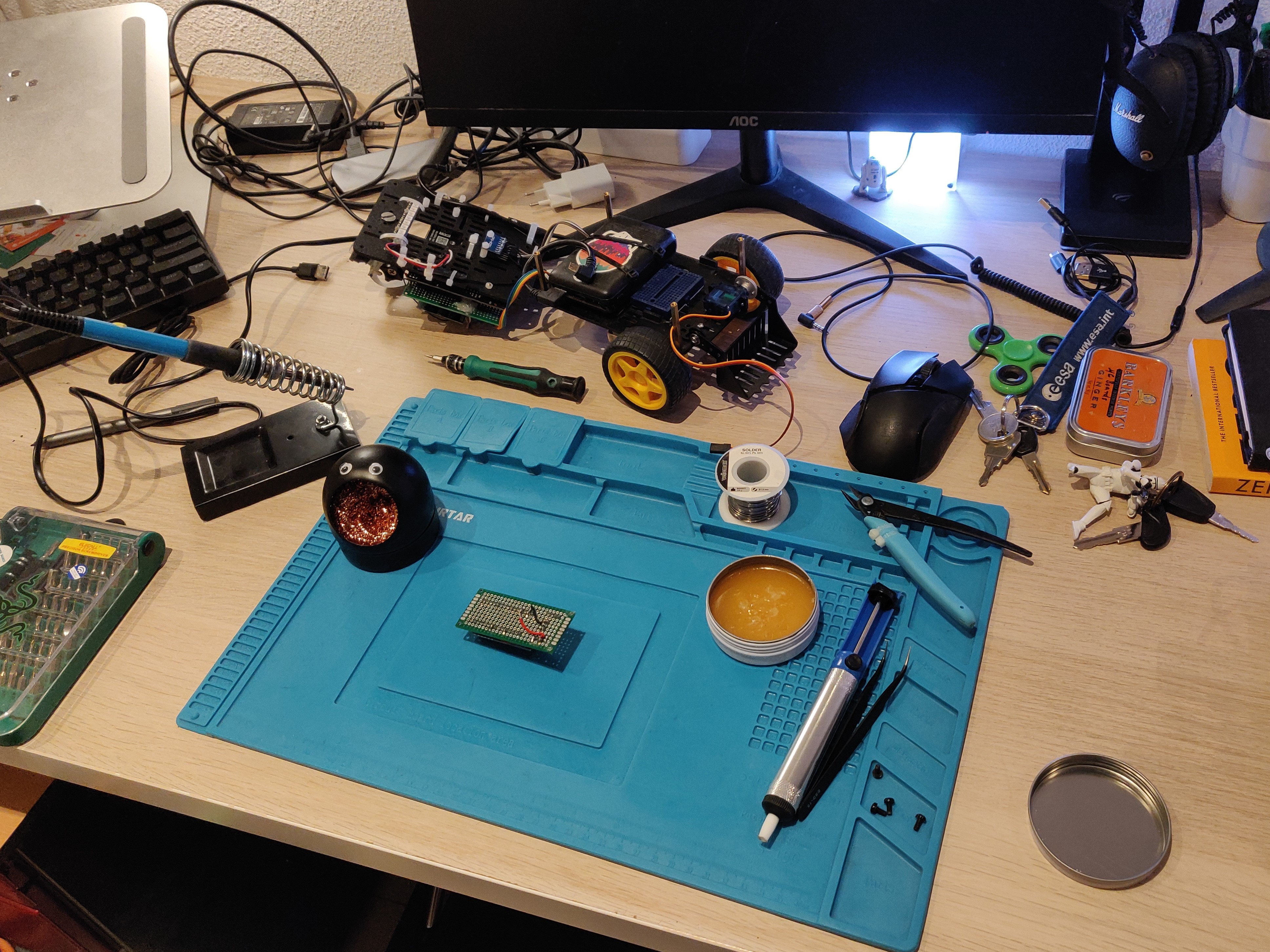
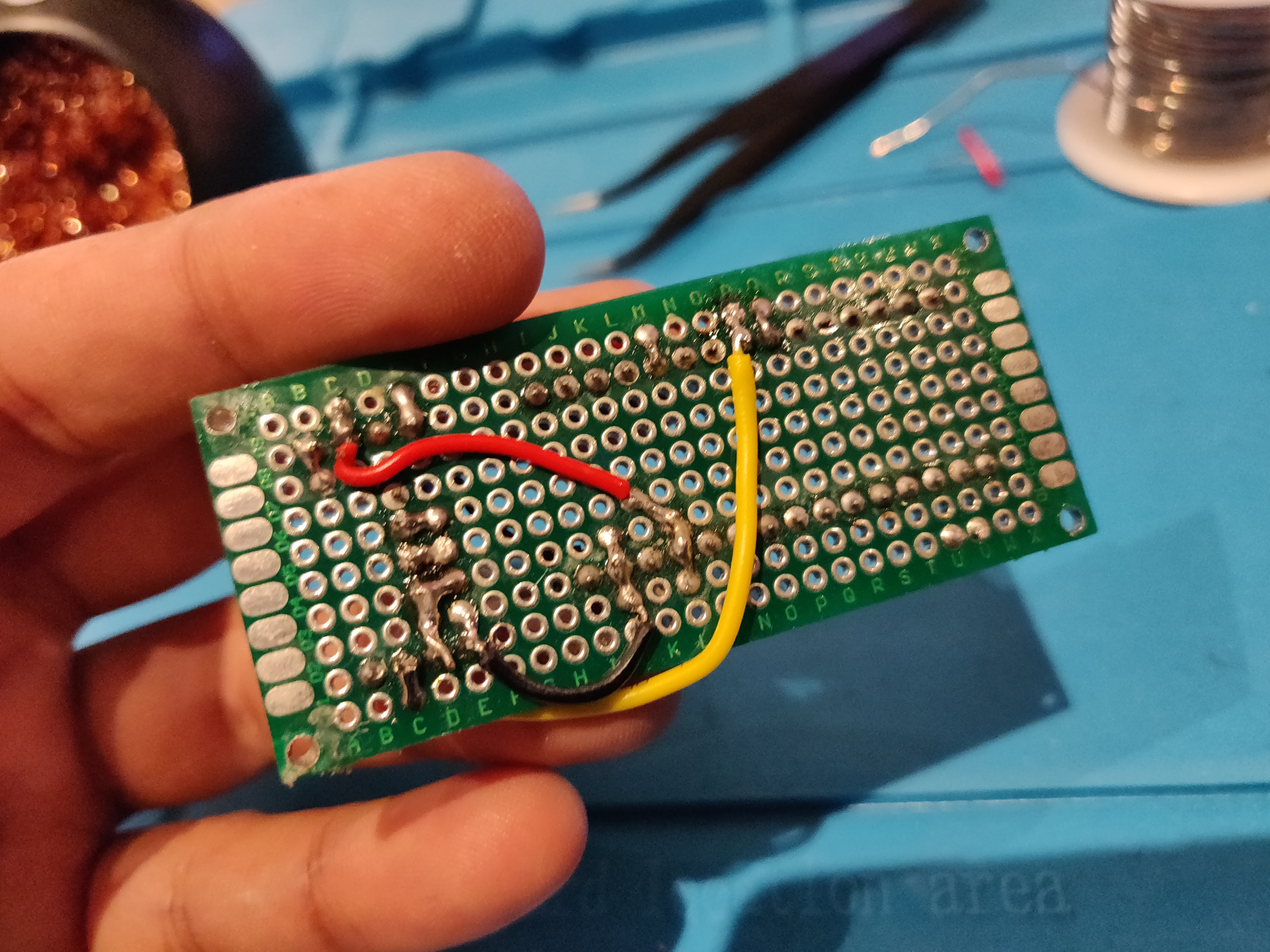
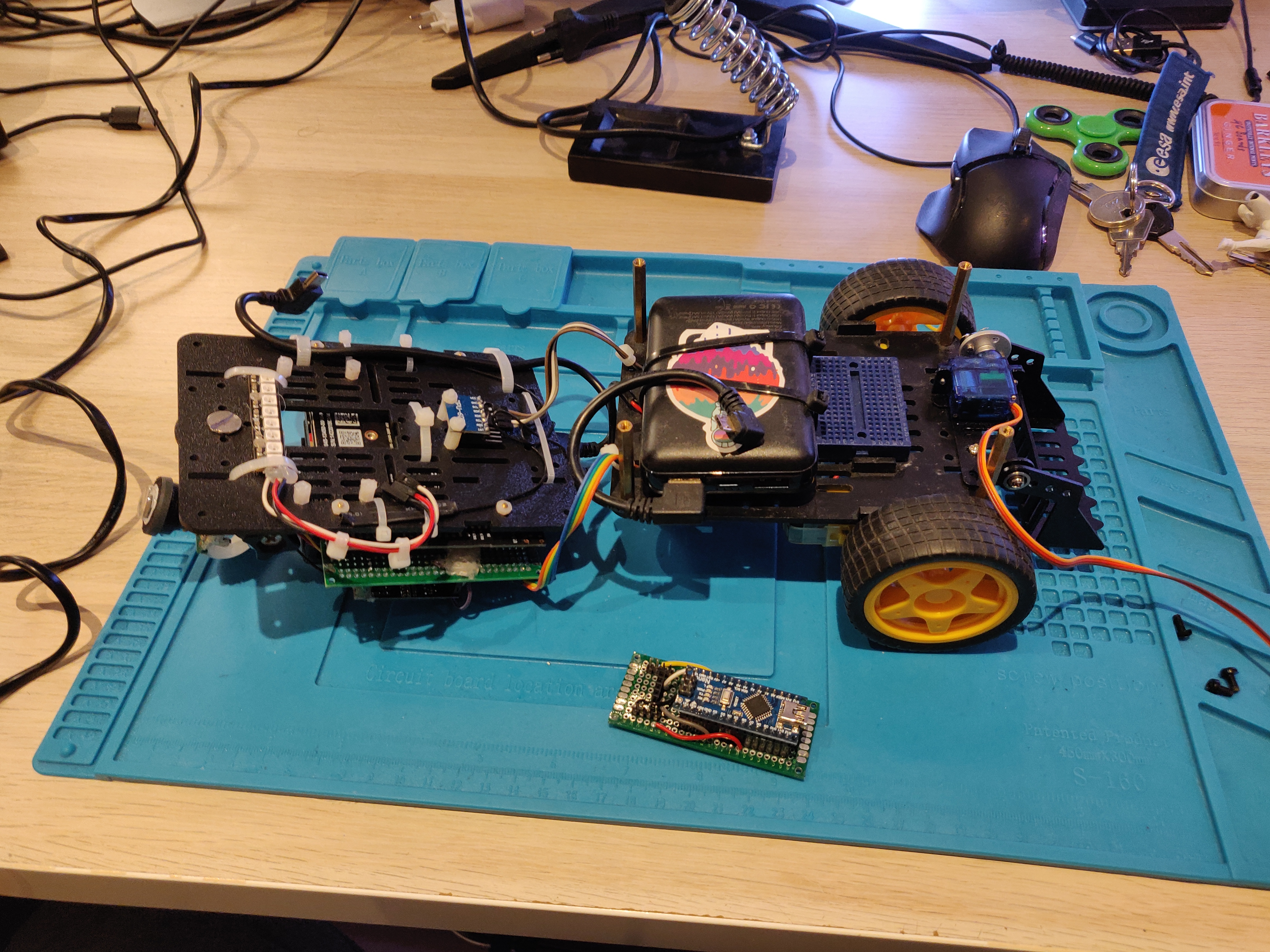
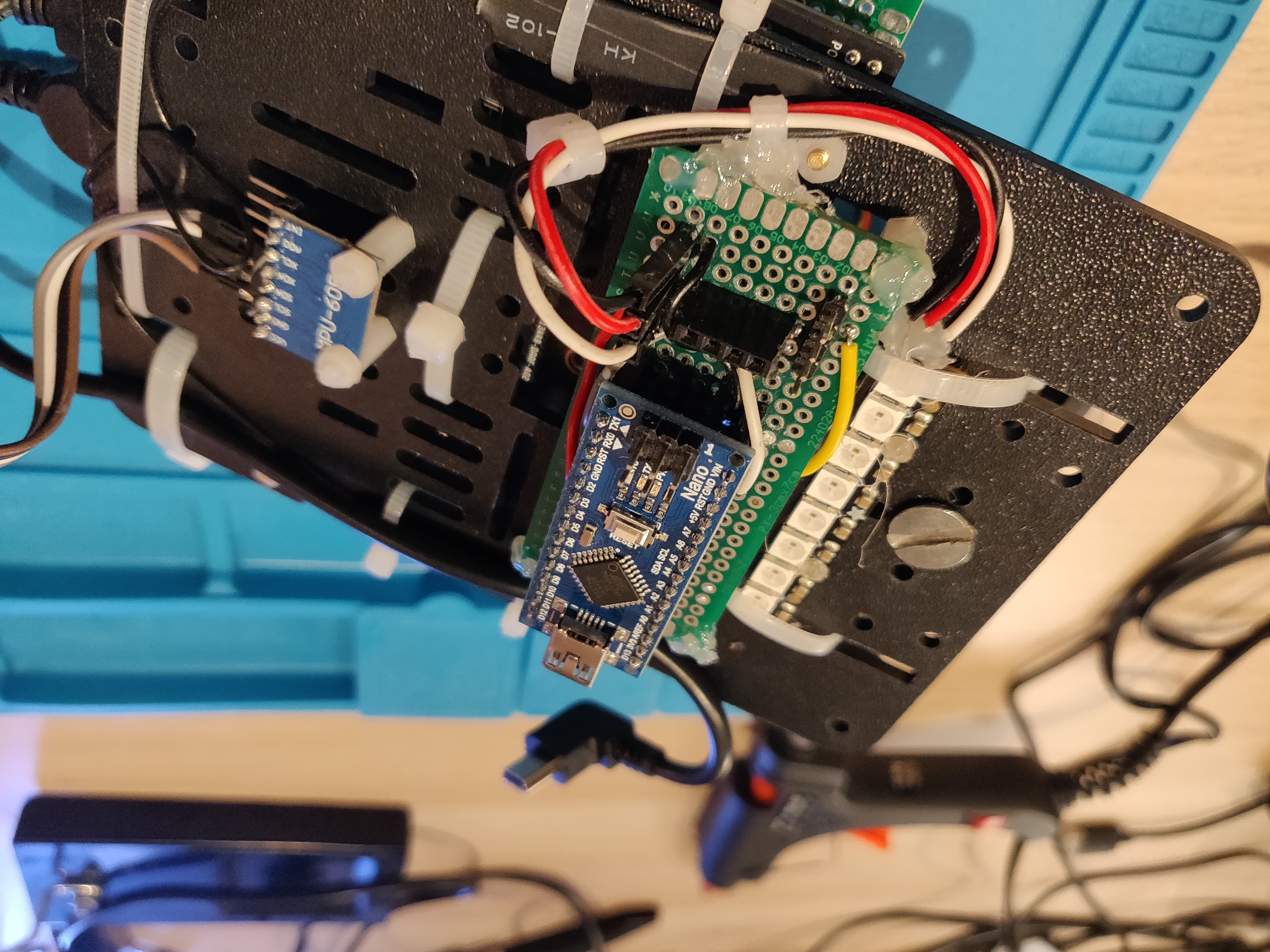
This was the easy part. The next step was to solder headers on to the proto board and connect them to the Arduino. For this, I had to disassemble the robot, pull the proto board from under the top baseplate, change the soldering and then mount it back. Following are some pictures from this process:
Once everything was assembled back again, it was time to turn the robot back on to see if everything was still working. The lights turned back on, so everything was alright:
The final, and the most challenging step was to program the functionality. I started with mapping the buttons in the joystick node: R1 for UP, R2 for DOWN and adding a publisher of Int8 message type to publish which button was pressed - 1 for UP, 2 for DOWN, 0 when either both buttons are pressed or none of them are pressed. The control switcher node subscribes to this topic, as well as the loader command topic published by the autonomous node and switches between them based on which mode the robot is operating on. In mode 0 (init mode, used for testing), the loader cannot be used (for now). In mode 1 (full teleop) and mode 2 (semi-autonomous), the user has full control over the loader and the commands from the joystick is used. In mode 3 (fully autonomous), the commands from the autonomous node are used (this will be added later, currently unused). Either way, the switcher node publishes one of three integers: 0 for STOP, 1 for UP, 2 for DOWN. These are subscribed by the ROSSerial node which sends these messages to the Arduino.
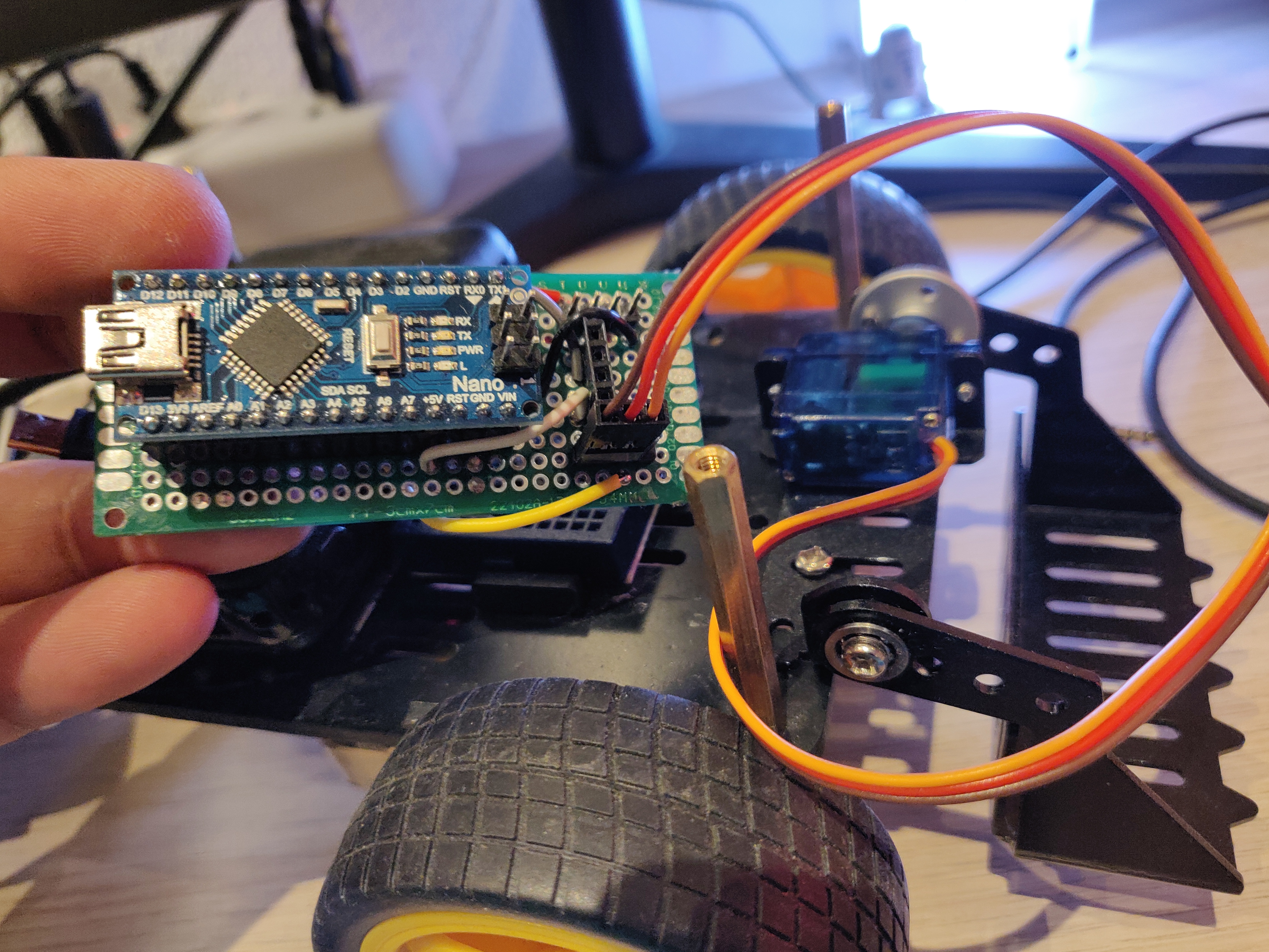
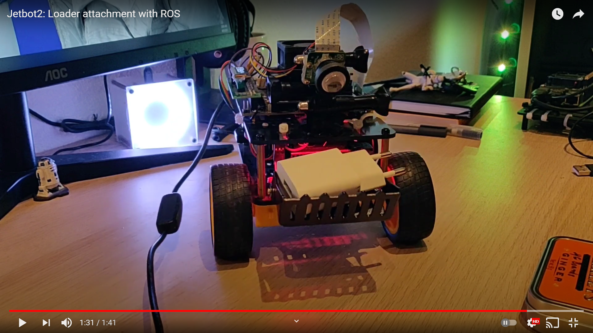
On the Arduino, a subscriber is initialized which reads the output of the switcher node. Based on whether the command says up or down, the servo moves to fixed angles in its upper and lower limits (pre-defined in the code). It was decided to make discrete actions instead of continuous, shorter steps because the Arduino didn’t seem to handle it, with the ROSSerial, Servo and Neopixel libraries being used. Here’s a video of the robot with the loader in action:
Many people have asked me, why did I add the loader? What am I going to do with it? The answer is: I don’t know. The loader was just an impulse buy and the truth is, I realized I could assemble it last weekend only because I found the part while cleaning my workspace. So, probably no more Jetbot2 updates for a while, unless I find another long weekend to spare. Now, back to implementing RTABMap on the OAK-D.