Since my last update, I haven’t really worked on the ESP32 robot other than just driving it around my room. However, I’ve been thinking and sketching different ideas for the eventual PCB and 3D printed chassis. I wanted the robot to be 4WD, but also low cost, and compact. For the first step, I decided to make requirements for a PCB. To start off with, I decided on using the ESP32 instead of the teensy because of the ESP’s Wifi and Bluetooth capabilities. However, in last post I mentioned that there weren’t enough pins on the ESP-32. I needed 12 PWM pins (3 pins per motor) to drive the motors and 8 interrupt pins (2 pins per motor) to read the encoders. This won’t leave any spare IO pins for peripherals.
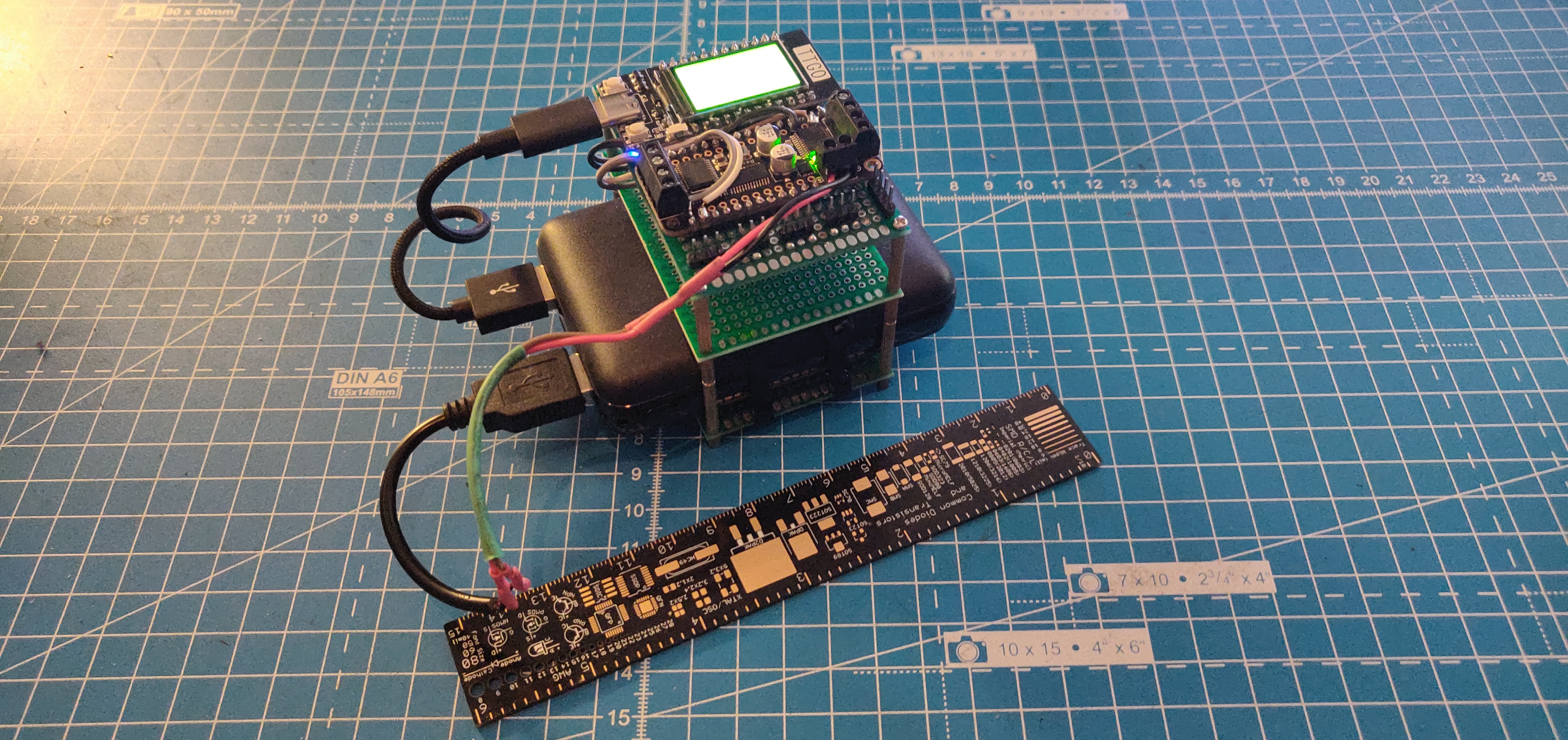
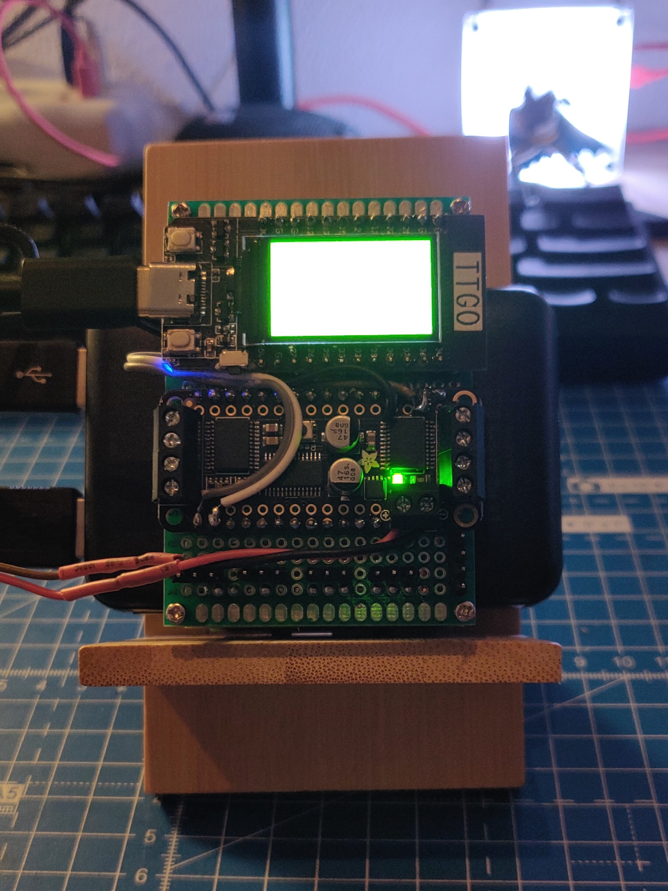
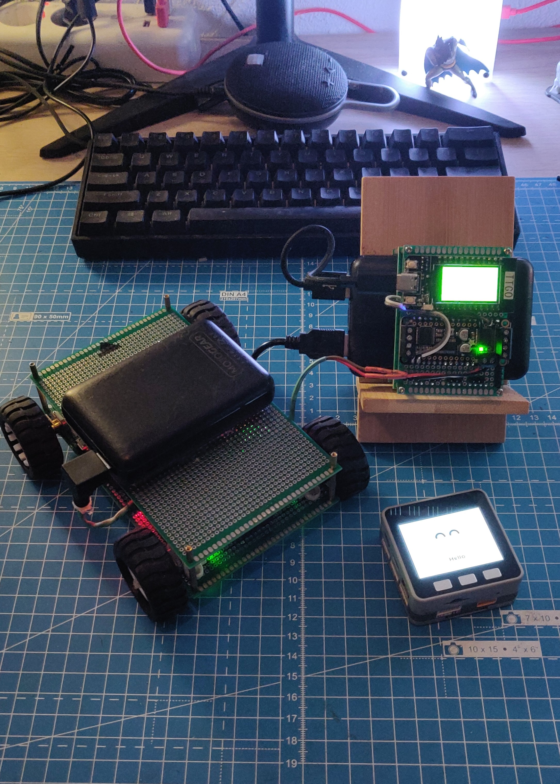
However, if I run the motors using I2C, I would need only 4 cables from the ESP32. So, I decided to use the Adafruit DC Motor Featherwing. I salvaged it out of the Jetbot2 (which was gathering dust in a corner) and soldered it alongside an ESP32 development board called TT-GO. Its an ESP-32 board with an onboard OLED screen. I was looking for an ESP32 board with a screen so, this at least ticks one box. I added an MPU6050 IMU on the same I2C bus and voila, I had the same platform as last post, in a much more compact form. Here are some photos:


This is when I realized that all my efforts were for nothing. I found

My next step is to start playing with micro-ROS, do some tutorials, examples and build my own applications. I want to try it out on all three platforms. As of now, I know micro-ROS works on the ESP32 Dev Kit C. I’m still unsure about the TT-GO, while there are quite a few articles about microROS and the M5 Stack Core (although these are in Japanese). Meanwhile, I’m also starting to design an enclosure for the electronics, battery, 4 motors and their encoders. So, more progress about this soon. Meanwhile, I’ve updated the design of the AKROS holonomic robot, and I’m taking a week off my regular job to work on it, I’ll explain these details in another in a couple of weeks.