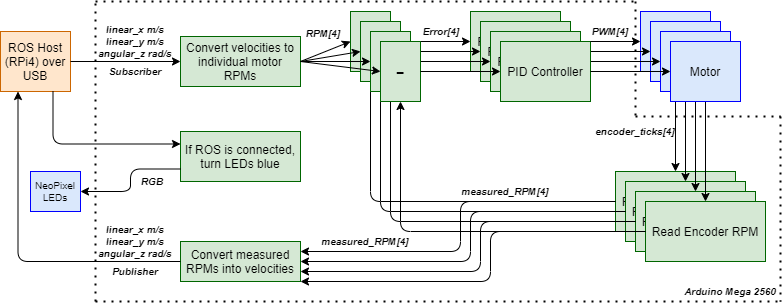
After setting up the encoders last week, I finally implemented closed loop control using classic PID controllers. I used four PID controllers, one for each motor to reduce the error between the reference RPM and the measured RPM from the encoders. The reference RPM is calculated for each motor from the Twist message velocities (linear velocity along x direction, linear velocity long y direction, angular velocity about the z axis) and the holonomic drive kinematic equations, and the measured RPMs are computed using the encoder readings. There are multiple PID libraries available for this, the most common being the PID_v1 library by Brett Beauregard, which comes with an excellent set of articles explaining it. However, I was unable to get it working on the Arduino Mega. So, I decided to write the PID function directly in the Arduino sketch. The PID output is the sum of the error, its derivative, and its integral, each scaled by KP, KI and KD (PID gains) respectively. The derivative and integral can be calculated easily - by subtracting the error from the previous error and dividing it by the elapsed time, and by adding the errors, respectively. In order to prevent the integral from getting too big, I also included a condition to reset the integral value if the reference RPM is zero. After several iterations, tuning and testing, the PID gains are:KP = 0.65, KI = 0.25, KD = 0.50. The same values were used for all four PID controllers
Tuning the PID controller: While there are multiple documented approaches to tuning a PID controller, I chose to use the approach that has always worked very well for me, especially when there are no strict control requirements. I unfortunately cannot remember or find the name for this strategy but its a simplified version of the Ziegler-Nichols tuning method, here it is as follows: First, set KI and KD to zero, and start tuning KP. Keep increasing KP till the reference value (setpoint) is almost reached. It’s okay if there are still oscillations, as long as they are steady. Once KP is tuned sufficiently, next step is to increase KD values until the oscillations go away. Once KD is tuned, KP is increased slightly, then KD and this cycle is repeated until increasing KD fails to stop the oscillations. In this situation, KP and KD values are at their optimum. If everything is okay, a PD controller should be more than sufficient, but now the KI value can be increased till the desired setpoint can be reached, with a desired amount of oscillations. There are a few other considerations in this method that I found online: first, make sure that the KD value is not too high, this will cause the system to vibrate at a frequency higher than the KP oscillations, which makes it chatter. In this situation, its best to reduce the KD value. Second, when increasing KI, there might be a situation where the oscillations grow bigger over time, in this situation the KP value must be reduced. Following these steps, and using the tuned PID gains mentioned above, provide the below results.
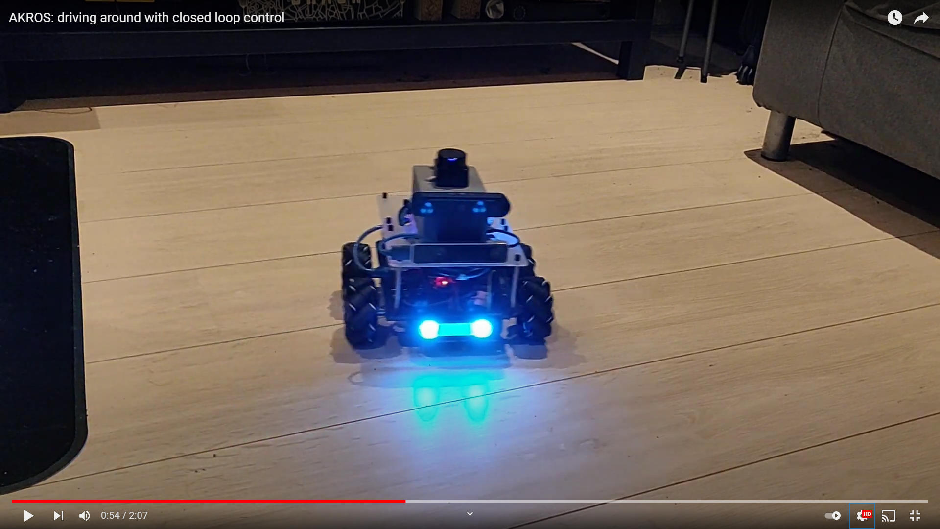
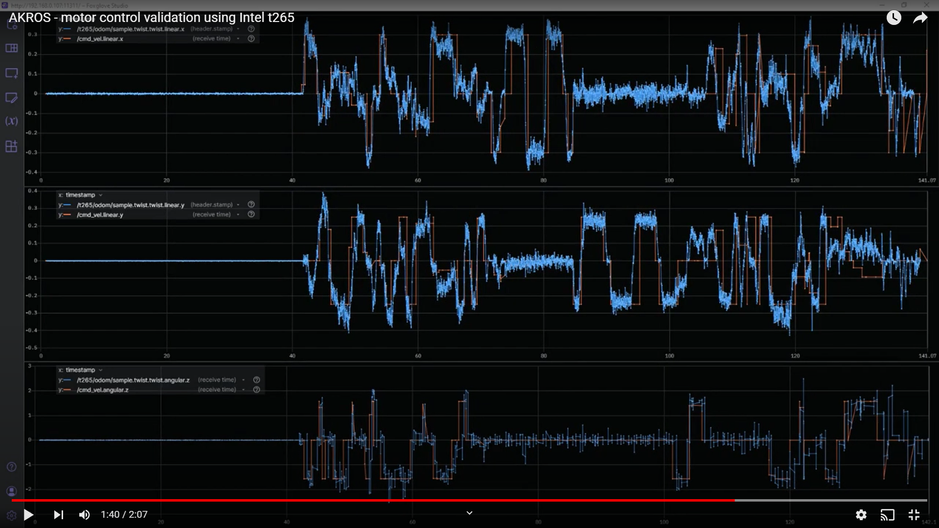
Validating the PID controllers: In the above video, the robot is provided with twist values from the AKROS teleop node. The twist velocities are constrained to 0.35 m/s for the x direction, 0.25 m/s for the y direction and 1.57 (or Pi/2) radians/s. In order to accurately validate the controller, I needed to compare/plot the reference RPMs and the measured RPMs. Since the conversion from twist velocities to RPMs (and vice versa) are linear, invertable functions, I could also simply compare the input twist velocities with the measured velocities by converting the measured RPMs. I decided against testing it directly from the Arduino, but instead decided to publish the measured velocities to the ROS host (the RPi4), and compare them using ROS tools. Something like the diagram above. However, in my implementation, the serial bus seems to be overloaded, hence causing the publisher from the Arduino to stop publishing after a while. This may be because of the high baud rate or the low buffer sizes that I am using. I still need to investigate this..I also have a colleague working with a similar applications, so I will wait and see if they have any luck. For now, I decided to compare the provided twist values from the teleop node, and the odometry sample from the T265 which implements visual-inertial odometry. While I didn’t expect it to be an accurate validation as there would be some extra noise, the results below indicate that the PID controller is sufficiently tuned.
Next steps: As an extra test, I also ran the autonomous navigation/exploration nodes (from previous posts) and they also showed improved performance because of this addition of closed-loop control. I believe I can tune/configure the local/global path planner parameters further to get even better performance. I will add a video in a future post. For my next steps, I continue with my goal of replacing the T265 with the OAK-D, by implementing visual-inertial odometry. My first goal is to make sure the inertial part is working well - so I plan on playing with the OAK-D IMU publisher to see if I can somehow improve its accuracy by filtering out noise. I also want to be able to publish the measured velocities from the Arduino back to the RPi, so that I can fuse this with the OAK-D IMU using an Extended Kalman Filter. This will give me a sufficient intertial odometry estimate and I should already be able to remove the T265. Another piece of the puzzle is the ros1_bridge. This will let me run ROS1 processes with ROS2. I intend to use this while I am porting my work to ROS2 next year. This lets me port one package at a time to ROS2 while maintaining the ROS1 parts. So, before I go on my holidays, I at least want this working, so that I can start with the porting once I’m back. More updates next weekend.