Its been a long time since I last posted on this blog. Mainly because things got busy at work, and I was also re-doing a lot of the OAK-D implementation that I have already spoken about. But since the last week, I have been working towards implenting wheel odometry using the quadrature encoders attached to each motor in the AKROS build. In this post, I talk about both the OAK-D upgrades and the odometry implementation.
OAK-D Updates: I was unable to use the OAK-D for a while because I had accidentally deleted the on-board calibration and I was unable to get a good calibration from my own calibration scripts (I was trying to calibrate the depth and RGB separately). I realized there was an issue was with my calibration scripts, and decided to try the calibration scripts provided by Luxonis. These worked like a charm and using a Charuco board, I was able to calibrate the OAK-D successfully and also flash the calibration readings to the on-board EEPROM. Meanwhile there were also changes to the OAK-D ROS drivers - Earlier, I had to provide the camera calibration matrices using a yaml file, but now I am able to read the calibration readings from the EEPROM directly. Thanks to a PR from a contributor, the IMU readings were also accessible. Finally, I was able to create a node that worked in two configurations - RGBD-Inertial (with RGB, Depth, and IMU streams) and Stereo-Inertial (with L/R Camera Images, Disparity, and IMU streams). Using these streams, I was able to use the depth_image_proc nodelets and the aruco_detect node to generate pointclouds from the depth image and to detect Aruco markers from the RGB stream, respectively.
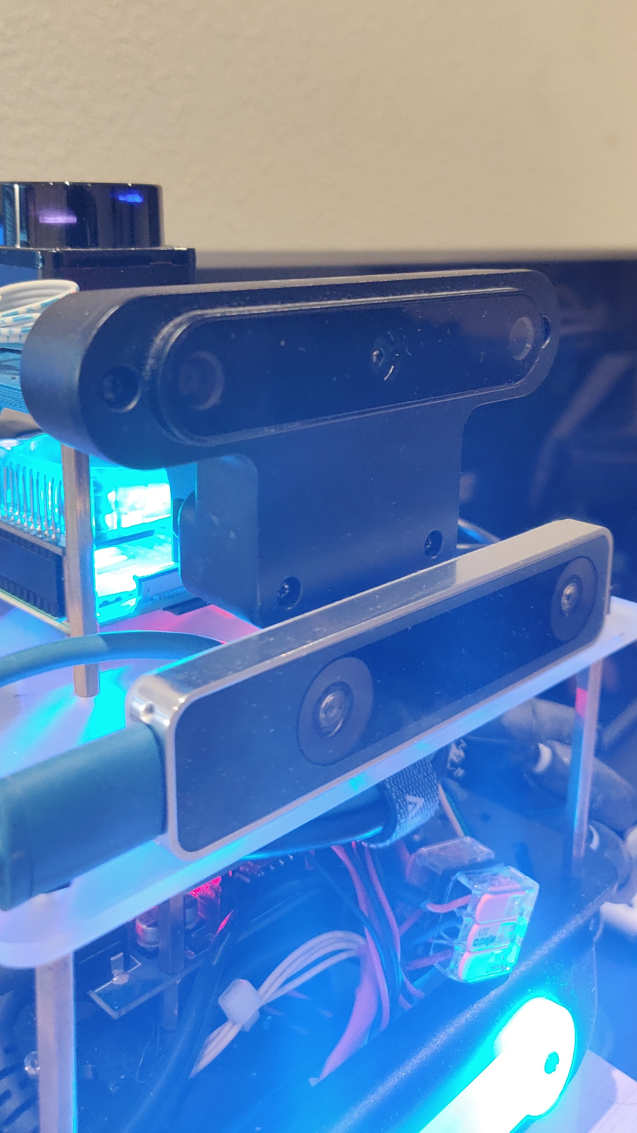
OAK-D connected to the AKROS navigation module mount. Results from the pointclouds and Aruco detection can be seen in previous blog posts here, here, here and here.
These work as a charm for now, but there are a few things I would like to update/fix:
- RGB-Depth Align: This is currently a WIP at Luxonis according to their developers, so hopefully there should be a working implementation soon. Currently, I am able to generate RGB depthclouds but only using the RViz DepthCloud plugin that superimposes RGB images onto depth images.
- Resolution/FPS: Other users seem to be having issues with getting a steady FPS from the OAK-D device for various resolutions and configurations on the RPi4. I have not experimented with it, but I would expect some issues in this area as well.
- AI: Currently, I am not using any AI, I am only publishing the streams. I want to use AI for 3 things - object/obstacle detection and tracking, semantic segmentation (ground detection), and fiducial marker (Aruco, AprilTag) detection. I first need to investigate if all three are currently possible on the OAK-D either individually or together. I also need to learn how to implement them, so its a future project on its own. Currently, I have Aruco marker detection implemented as a node on the RPi4, but I would prefer if it happens on-board the OAK-D.
- IMU: I am not using the IMU for now but I would like to fuse it with the wheel odometry and use the results as the main odometry to improve the localization.
- Nodelet: I tried making the OAK-D node as a nodelet, which worked on its own. But nothing was published when I used the same nodelet manager for the depth_image_proc nodelets. I need to investigate this further and fix it later..
- The OAK-D nodes work like charm on the Raspberry Pi 4 as a standalone node. I believe OAK-D + RTABMap would work well together on the RPi4 8GB as well. Unfortunately, the OAK-D nodes + the ROS Navigation Stack together are computationally very expensive, and end up making both processes extremely slow. In my opinion, a separate Raspberry Pi 4 to process the OAK-D data and a separate RPi4 for the Navigation Stack is the way to go. Maybe I should go for the OAK-D-CM4 device which comes with a RPi4 compute module 4 attached.
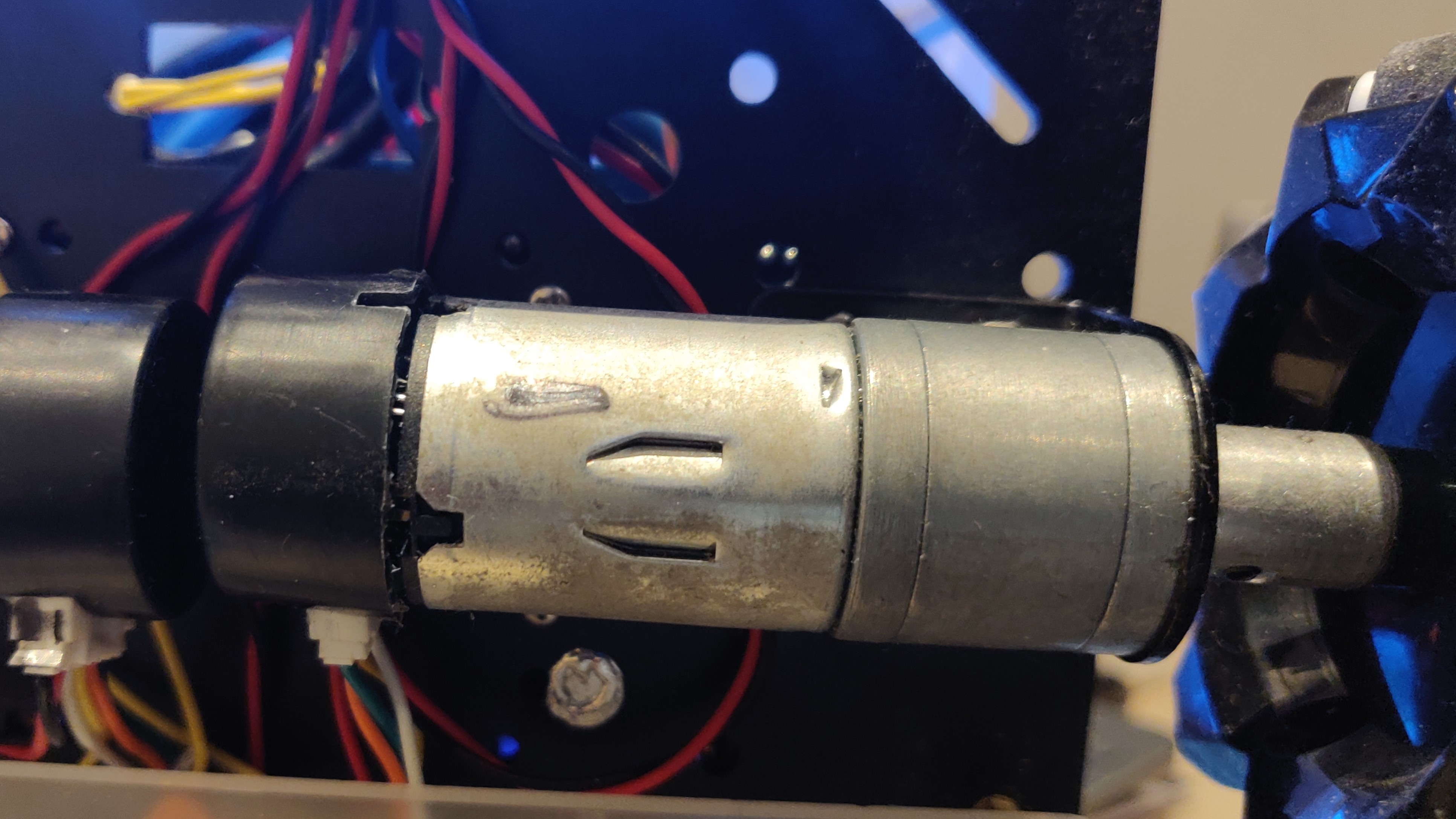
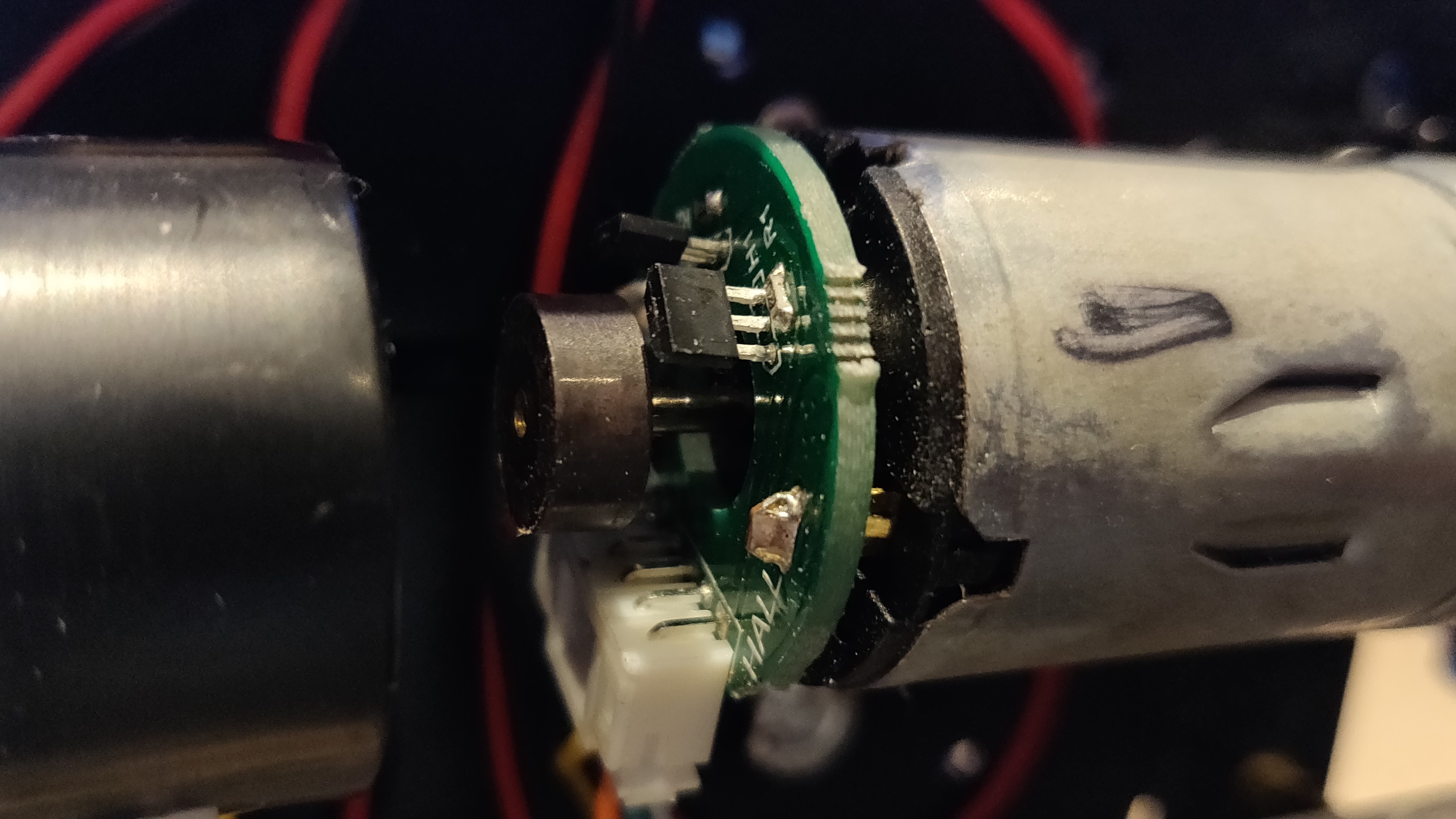
Wheel Odometry Implementing the wheel encoder odometry did not need any hardware changes to the robot. The motors in the base kit already had quadrature wheel encoders attached, but I had not wired them at the moment - so this was my first step. Quadrature encoders are made up of a spinning disk and 2 hall effect sensors and have 4 wires - 1 for Vcc for the hall effect sensors, 1 connected to ground, and 1 pin for each of sensors. To start with, I bundled up the Vcc pins and the ground pins from each of the 4 motors and connected them to Vcc and Ground on the Arduino. This left me with 8 encoder pins - which was a problem because the Arduino Mega has only 6 interrupts.
For a long time, I considered multiple options - either switch to a Teensy, where every pin has interrupt capabilities or spend some time understanding the PinChangeInterupt (PCINT) concept on the Arduino and implement it. This was till I found the Encoder library by Paul Stoffregen - This library counts quadrature encoder pulses and also worked if one or none of the encoder pins are interrupt pins, but this works at lower resolutions. So for the remaining 8 wires, I connected the first wire from each sensor to an interrupt pin, and the 2nd wire to a non-interrupt digital pin. I used this library to read the number of ticks from each encoder. I then wrote a function to compute the RPM from the encoder ticks, but later, inspired by the LinoRobot project, I moved it to the encoder library itself.
The next step was to calculate the linear and angular velocities from the individual wheel RPMs. In order to move the robot, we first get the linear x/y and angular z velocities, which are then mapped to RPM values for each motor using the kinematic equations for the AKROS platform. This results in the values below:
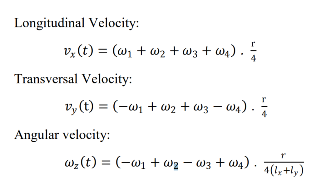
In the odometry scenario, we need the inverse of this system - we use the RPM values from each motor to calculate the linear and angular velocities of the robot. These computed velocities must match the input velocities but will never be exactly the same because of lots of reasons - wheel slip, rounding errors to name a few. For this, we need a controller (PID for example) to minimize the errors measured velocities as close as possible to the input velocities. This will be the next step of this project.
For now, since I had the computed velocities of the robot, I also need to send this back to the ROS host (the RPi4 in this case), so that this could be fused with the IMU to get odometry information. So, using rosserial I decided to write a publisher, in addition to the existing twist subscriber. The Arduino-ROS communication is limited by the bandwidth of the serial bus, so I decided to reduce the size of the published object by chosing to send it as a geometry_msgs/Point message. This is a structure with only 3 variables used to describe the coordinates of a point, but in this case x, y and z indicate linear x, linear y and angular z velocities. Unfortunately, this does not work entirely. The publisher publishes messages for some time and then completely stops publishing. I believe this is because of the subscriber, because as long as it is not receiving any twist messages, the publisher works fine. Once the subscriber receives a few messages, the publisher doesn’t publish anymore. I need to play with baud rates and buffer sizes to see what works, but if that doesn’t work, I don’t know what else to do.
At least this will not stop me from implementing closed loop control because that happens on the Arduino and won’t need any publishers. So, this will be my next step. I also want to implement an Extended Kalman Filter to fuse at least the T265 odometry with the OAK-D IMU for starters. Hopefully the publisher works as well, so I can also fuse the wheel odometry. As its already December, I must also decide on how to spend my Innovation Budget - this is an annual budget my employer provides to find personal/hobby projects such as this one. Last year I bought a RPLidar and a Raspberry Pi4 for this project, but for next year I want to build something else, this time with a focus on active and passive depth sensing, RGBD SLAM and Visual-Inertial Odometry. For next year, I also want to focus on porting all the AKROS work to ROS2.