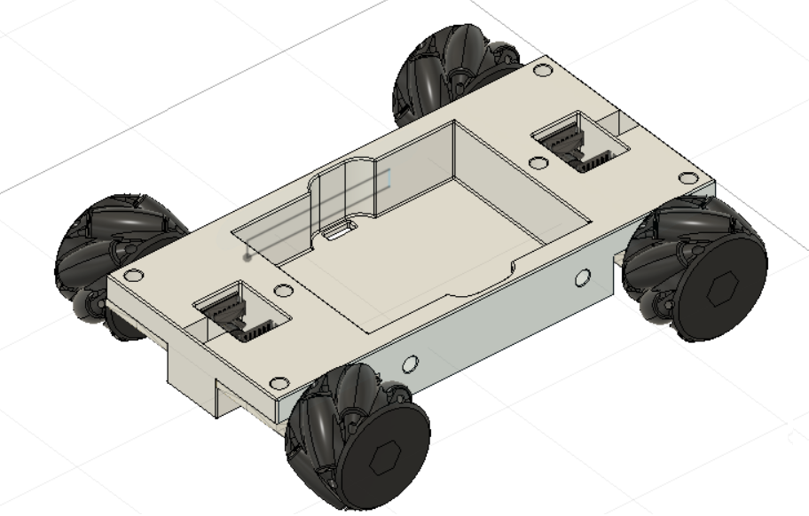
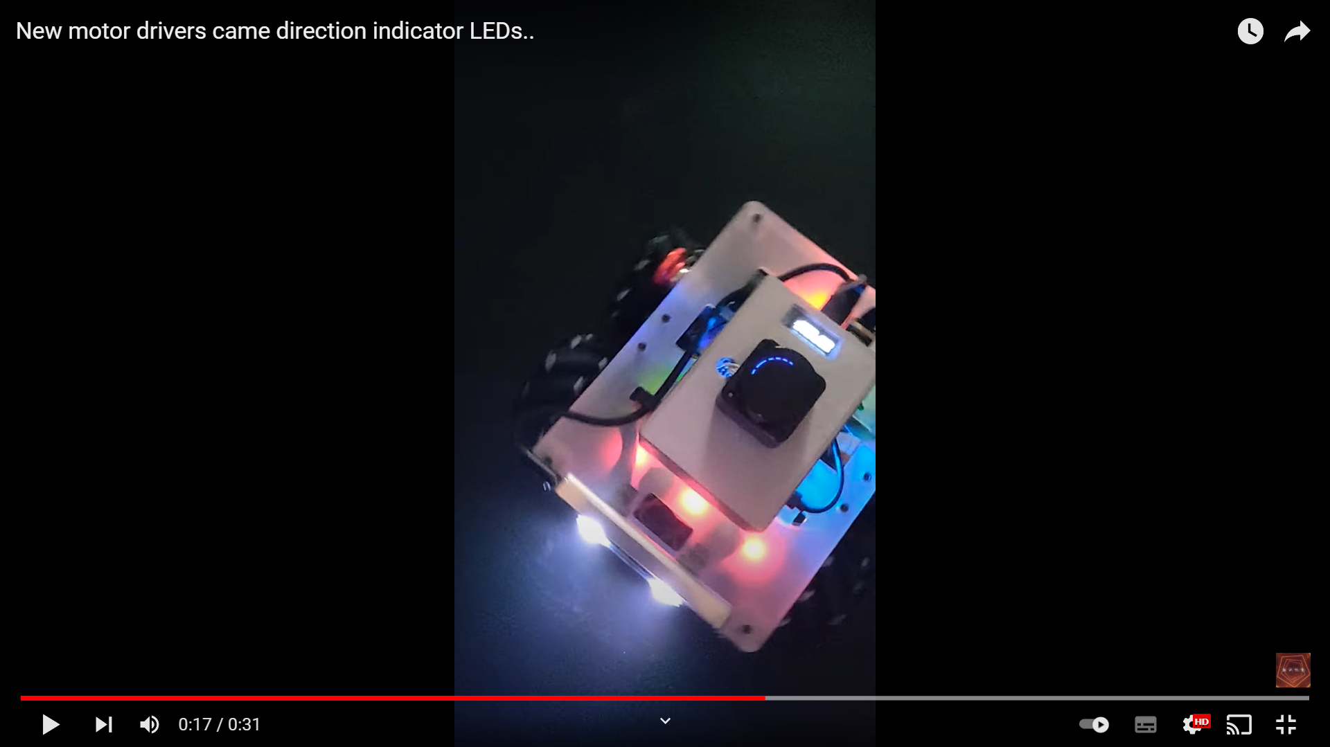
I finally got some extra time thanks to a long weekend, so I decided to bring the AKROS robot out of its box and make some upgrades. Last week, I received two Cytron MDD3A dual motor drivers which are compatible with the Teensy 4.1 Expansion board as I wanted. My plan was to remove the Arduino Mega and the 5V L298n 4 channel motor driver from the AKROS robot, replace it with the Teensy board and the Cytron motor drivers, then redo the wiring and modify/upload the code. I planned on using the same ROSSerial based code for ROS1 Noetic (ROS2/microROS is for later), but I wanted to use VSCode and PlatformIO instead of the Arduino IDE this time. Here’s how it went:
Step 1: Remove the Arduino Mega and the existing motor driver
This part went really quickly as I had done the exact same thing once before, so I knew what I had to do. I first clicked pictures of the existing wiring of the direction/speed pins, the encoder and the Neopixel pins. Once I had a picture of each cable and its original connection, I removed it. Once all cables were removed, getting the PCBs out wasn’t difficult - just a few screws and both the motor driver and the Arduino were out.
Step 2: Attach the Teensy 4.1 board and the Cytron motor driver
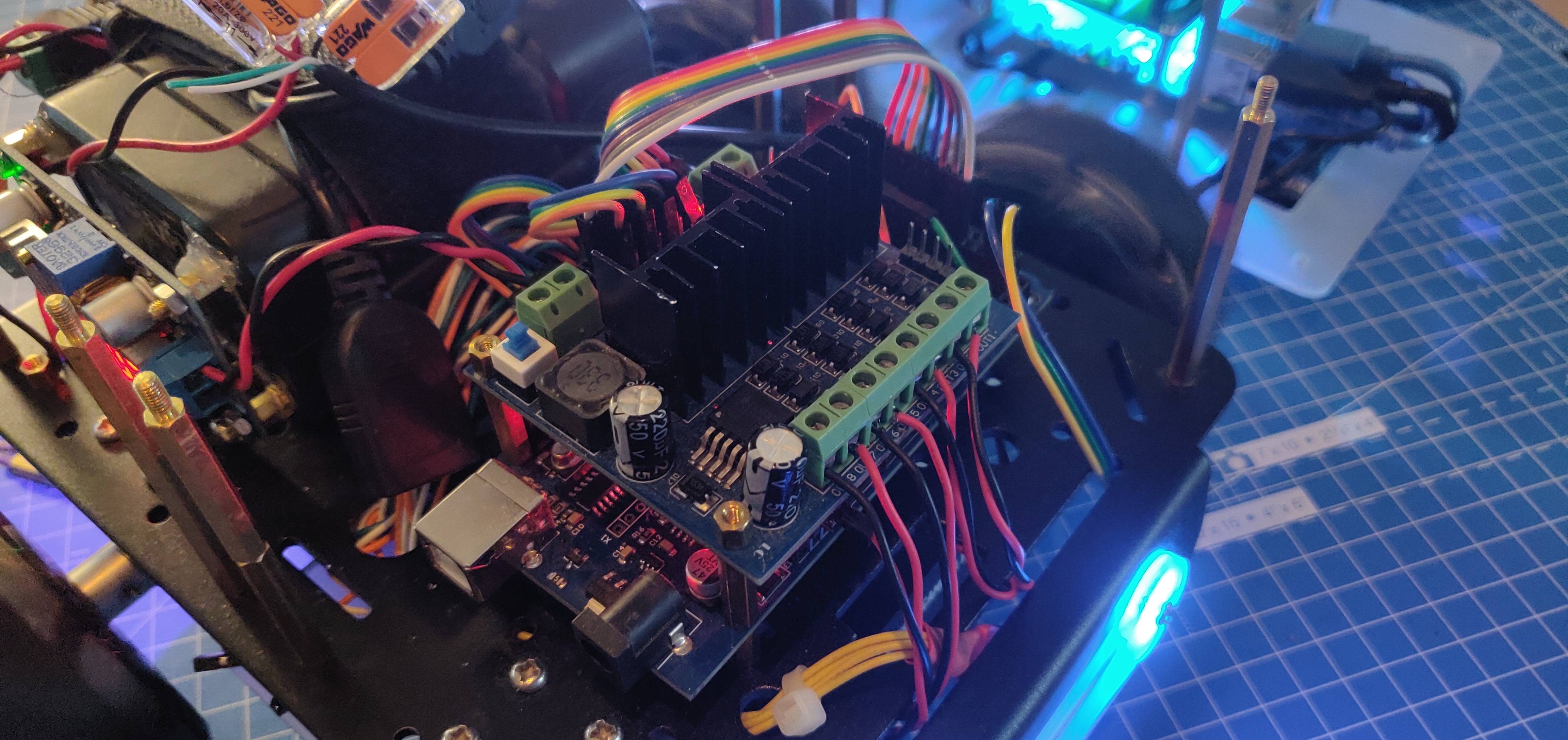
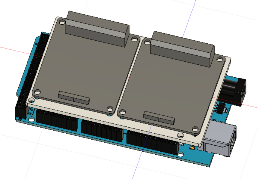
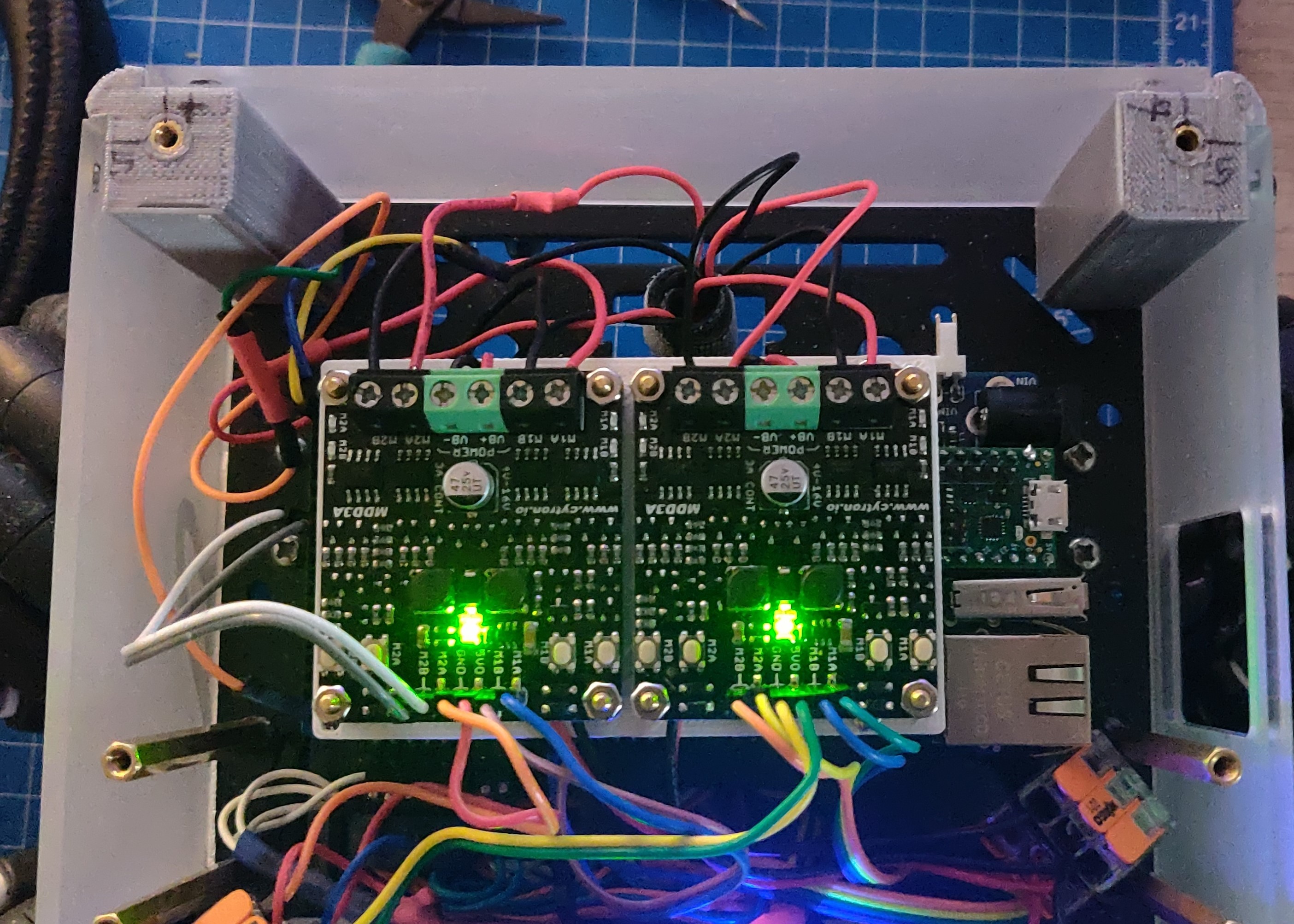
The Teensy board is in the same form factor as an Arduino Mega, so it was a direct replacement. However, unlike the original motor driver, the Cytron motor drivers couldn’t fit directly on top of the Arduino with just spacers as the holes didn’t align. So, I had to design and 3D print an adapter piece. Now, using spacers the adapter piece is assembled on top of the Teensy board and then the Cytron motor drivers are mounted on top of the adapter piece. Since the new motor drivers don’t have massive heat sinks like the old one, the entire assembly fits in the base module of the robot. All the header pins of the Teensy board are accessible with angled connectors, but with straight Dupont connectors, you need to bend the pin a little bit when the adapter piece is present. I could make some changes to the design to make space for the connectors, but for now it works.
Step 3: Wiring
This is the part which I thought would be a piece of cake, but it wasn’t. What I did not consider is that the MDD3A motor drivers are controlled using two PWM pins, and not two digital pins and one PWM pin like the L298n motor drivers. So, I couldn’t just redo the wiring with the same pins as before. Fortunately this did not affect all pins - the encoder pins and the Neopixel pins remained in mostly the same place. As for the motor driver, it used four fewer pins, so it did make some things easier for me. Once again, I meticulously clicked pictures of every step so that I knew not only the connection but also the corresponding pin numbers.
Step 4: Fixing the code
Once the wiring was done, it was time to fix the code. First thing I had to do was change my config file - I fixed the pin numbers for the Neopixel pin, the encoder pins and the motor driver pins. In this new case, each motor x has a Mx_a and Mx_b pin instead of also having a Mx_en pin. So, the Mx_en pins for each motor were also removed. Now, the functionality needs to be changed. In the original code, I have a function called spin_motor(int motor, double velocity) which rotates a specific motor according to an input velocity. Based on the direction, the digital directional pins are set and the absolute speed is written to the PWM enable pin. In the new code, the directional pins also set the PWM, so the code was changed and the enable pins were removed. The code difference can be seen here:
//Original Code:
//Writes digital/PWM values to motor direction/enable pins for the specified motor
void spin_motor(int motor, double velocity){
  if(velocity > 0 ){
    digitalWrite(inPins[2*motor], HIGH);
    digitalWrite(inPins[2*motor + 1], LOW);
  }
  else{
    digitalWrite(inPins[2*motor], LOW);
    digitalWrite(inPins[2*motor + 1], HIGH);
  }
  int motor_pwm = constrain(abs((int)velocity), MIN_PWM, MAX_PWM);
  analogWrite(enPins[motor], motor_pwm);
}
//New Code:
//Writes PWM values to motor pins for the specified motor
void spin_motor(int motor, double velocity)
{
  int motor_pwm = constrain(abs((int)velocity), MIN_PWM, MAX_PWM);
  if(velocity >= 0)
  {
    analogWrite(inPins[2*motor], motor_pwm);
    analogWrite(inPins[2*motor + 1], 0);
  }
  else
  {
    analogWrite(inPins[2*motor], 0);
    analogWrite(inPins[2*motor + 1], motor_pwm);
  }
}
Step 5: Uploading and testing
Uploading the code to the Teensy was extremely straightforward. Add the used libraries to platformio.ini or the lib directory, add the config file to the include directory, and add the Arduino code to main.cpp within the src directory, with a #include <Arduino.h> on the top. Then simply build and upload the code. I have created a template repository on Github what you can use to create your own ROSSerial/PlatformIO projects. However, it is important to note that I am using a modified rosserial_arduino_lib, if you want to use the original libraries (by Joshua Frank, and can be found here, please replace the link in platformio.ini.
However, I did have some concerns. In the past, when I have uploaded rosserial code from the Arduino IDE on my Windows 10 laptop, ROS Noetic has troubles connecting to the board and sometimes also displays the ‘version mismatch’ error. In this situation, I have usually found the Arduino installation on my RPi or Jetson Nano to be most reliable as they to link the correct ROSSerial libraries. I thought I could have the same issues with PlatformIO, but clearly I was mistaken. Everything works as expected, and every time I make some changes to the code or the rosserial_arduino_lib, nothing breaks on Windows 10 or when connected to ROS Noetic. There also seems to be no bandwidth issues as all publishers and subscribers were functioning really well all the time.
Once everything was working, I also made a small video showing the new motor drivers in action. The motor and drivers make a different sound and its probably more silent than with the previous motor drivers. The motor drivers also come with one green LED each to indicate power, and four red LEDs to indicate direction (one for each motor and direction). Thanks to the translucent walls, it makes the base module light up even more as shown in the video below. While some people seem to like it, I’m already considering new parts with black acrylic.
Step 6: Transition to ROS2
While my plans for the AKROS robot and the Teensy board is to implement microROS with ROS2 Galactic, it is still a long way off. I’m currently learning and experimenting with ROS2 and still need some time to start implementing it on my robot. I was planning on using the Nanosaur to learn ROS2 but now I have a few problems - the Jetson Nano does not turn on. I tried multiple base boards and also different expansion shields but nothing worked. I have two power banks and neither of them work. The second issue is still the 3D printed front cover - still haven’t had the time to print a replacement for it. So I’m keeping the Nanosaur aside for now, I can certainly reuse the parts if its needed, but I will keep it assembled for now. Meanwhile I started by forking and building the linorobot2 project alongside the ROS2 demos and examples. Since the linorobot2 can also be configured to run on a mecanum wheeled platform like mine, I decided to continue using this as a tool for learning ROS2 and also as a reference for porting the AKROS stack to ROS2.
Meanwhile, I also have some intermediate goals with the AKROS robot. For starters, I have a microSD card reader on the Teensy on which I have a 16GB microSD card. I want to experiment with this, and use it to potentially store the config file or for data like diagnostic logs or trajectories. Secondly, I want to add an IMU to the Teensy board to improve odometry from the low level controller. When the robot gets stuck, the motors can still rotate freely, which triggers the encoders and hence the odometry estimate is no longer correct. The IMU can fix this as it can detect that the robot has not moved and correct the encoder odometry estimate. Finally, I want to interface a (Flysky) RC receiver to it so that I can control the base module without the Raspberry Pi. The goal here is to have the Raspberry Pi only for the navigation module and SLAM, while the base module is responsible for motion control, teleoperation and some local state estimation.
The next build
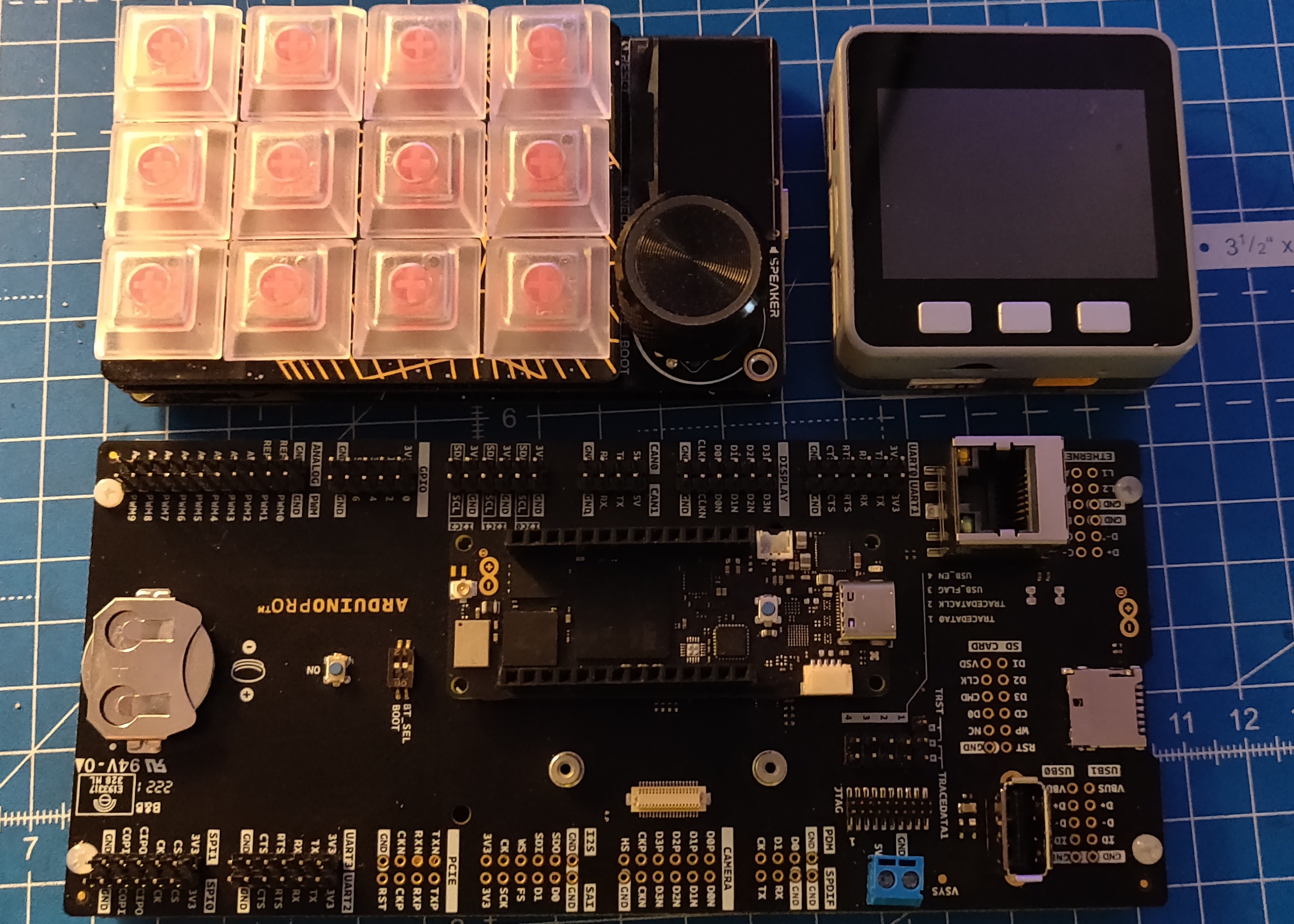
For my next build, I definitely wanted to make a bigger robot and work with some BLDC motors like hoverboard hub motors. However, I don’t have a lot of space and its still a few months till I move into a bigger apartment. So for now, the next build has to be smaller. Since the last few months, I have also been working on a low-cost, miniature version of the AKROS robot. I want to take my time and be really detail oriented with this one as I want to potentially start selling it as a learning tool. I also want to keep it simple and use a microcontroller instead of a Raspberry Pi or an Nvidia Jetson device, as I want this robot to be controlled over wifi using an external host computer. While I have worked out most of the details, one thing that I’m still struggling with is the microcontroller selection. I’ve been playing around with some microcontroller platforms this past week, like - ESP32, Raspberry Pi Pico RP2040, the Teensy 4.1 (with the expansion board) and the Arduino Portenta H7
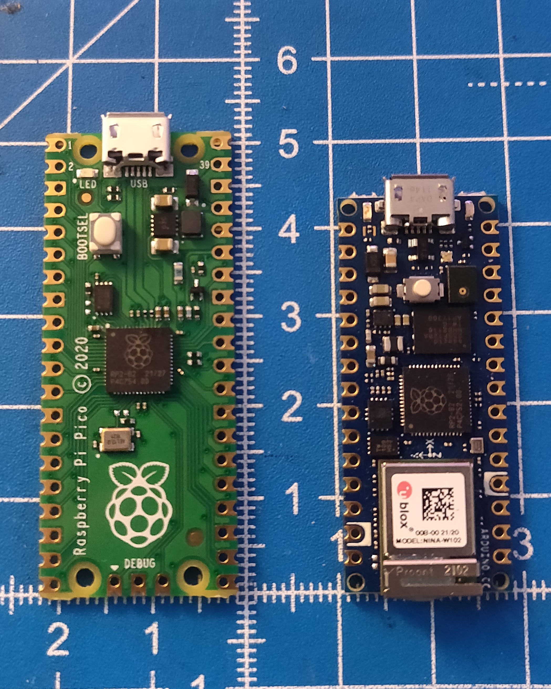
The Teensy 4.1 board is for the AKROS2 project I explained earlier, so I will ignore this for now. The Portenta is definitely overkill for this project, so although I’ve tested that it works, it is going back in its box. I’m now left with the ESP32 and the RPi Pico, and I’ve been struggling to choose between the two - mainly because of Wifi and Bluetooth which the ESP32 provides but the RPi Pico does not. On the other hand, there’s the Arduino Nano RP2040 Connect, which is a RPi Pico with a NINA-W102 Wifi/Bluetooth module (that has an ESP32 in it) and a few extra features put together by Arduino. It costs twice as much as some ESP32 boards, but it comes with an onboard microphone, a six axis IMU, 16MB Flash, and is also possibly more reliable than most ESP32 boards in terms of documentation, support and community. The Nano RP2040 also costs as much as a RPi Zero 2 W + a RPi Pico + IMU (including tax and shipping), which is a combination I can try, but the RPi Zero 2 W and the popular IMU chips are out of stock literally everywhere. I still have to make some decisions here, maybe I can start by drawing up a pros and cons list. Meanwhile, I have been busy trying to design the PCB for this project, I’ve got the schematic for the four channel motor driver, the battery/charging system as well as the sensors which will be added to the robot. Only thing remaining is the microcontroller which I still need to decide.
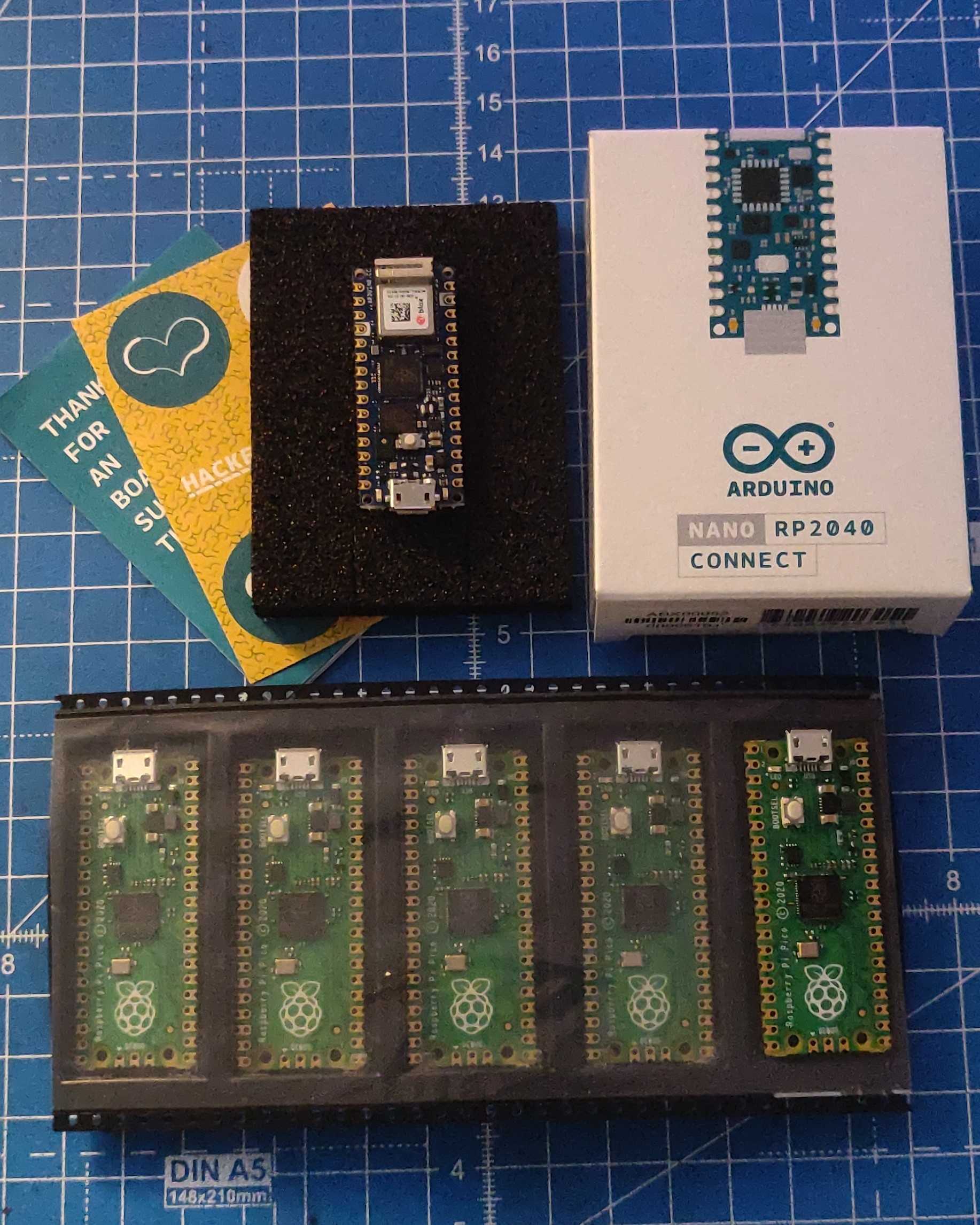
This week, I also received two new microcontroller devices - the Arduino Nano RP2040 Connect, and the Raspberry Pi Pico. I still haven’t had the time to play with them yet, although I did click some pictures and also used up the stickers the Arduino came with.
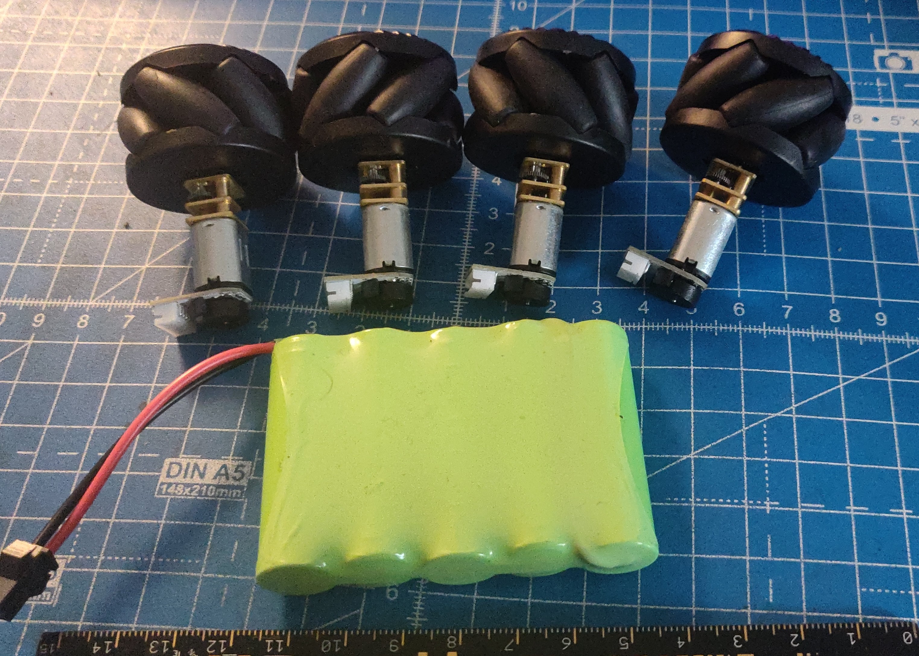
I have also been testing various N20 micro metal gear motors with different gear ratios and speeds, and I’ve ended up selecting some 100RPM motors + encoders with some decent torque. I also looked for some mecanum wheels, and found some really nice ones on Pimoroni. They’re made for the N20 motors, come in a pack of four (which is convenient) and are of really good quality. However, they are quite pricy (at around 24 Pounds for the set of 4 + shipping), and its a shame they dont sell them individually or in Left/Right pairs. I broke one of them due to my own fault and had to buy the entire set of 4 again.
For the next few weeks, I will continue playing around with ROS2 on Windows/VSCode and microROS using VSCode/PlatformIO. I have some ROS extension issues to fix in VSCode, and then I will also be able to use the extension for sourcing the underlay/overlays and building my workspace. I also want to test out several microcontrollers with PlatformIO and microROS - the Arduino Portenta H7 (for the legged robot that I haven’t forgotten about), the Raspberry Pi Pico, the ESP32 (using an M5Stack Core Gray), and an Arduino Nano RP2040 (these last three for the miniature AKROS robot). More updates next week…
