This week I experimented with the Arduino Portenta H7, the Arduino Nano RP2040 Connect, and the RPi Pico board, and tried micro-ROS examples with ROS2 Galactic. My goal was to implement a structured workflow for building and testing micro-ROS applications using these devices on Windows 10. Unfortunately, this proved to be a bit of a challenge, especially with my ROS2 setup on Windows. In my previous post, I had mentioned the two installations on my Windows system - a native Windows 10 installation using ROS2 binaries, and a Ubuntu installation on Windows Subsystem for Linux (WSL2). I still had some issues with the native installation, so I decided to uninstall it for now instead of spending too much time on it. The WSL2 installation is good for a lot of ROS2 experimentation, but I have been unable to access USB devices connected to the Windows 10 host using WSL2, so I cannot use it to build and upload micro-ROS code to microcontrollers. At least not yet, as I will explain later.
For now, my solution was to use micro_ros_arduino, which provides precompiled micro-ROS libraries for baremetal projects based on the Arduino IDE. It provides official Arduino support for the Arduino Portenta H7 and the Arduino Nano RP2040 Connect, support for Teensy boards based on Teensyduino, and community contributed support for boards like the Arduino Due. It is quite easy to use it, I simply downloaded the latest release for ROS2 Galactic as a .zip file, and added it to the Arduino IDE using the ‘Include library’ option. Then, code can be compiled and uploaded in the traditional way on the Arduino IDE. With ROSSerial, I also tried uploading code using the Arduino IDE on Windows 10, and then connected it to ROS1 running on Ubuntu, but I received ‘version mismatch’ issues quite a few times. I’ve had to uninstall and reinstall both the Arduino IDE and ROSSerial libraries to fix this issue. Fortunately I don’t have a similar problems with micro_ros_arduino and the workflow is very straightforward - I upload the code using Arduino IDE on Windows 10 directly without having to manually add the micro-ROS libraries each time, and then I can connect it to any ROS2 device and I am good to go.
Arduino Portenta H7 (Serial Transport)
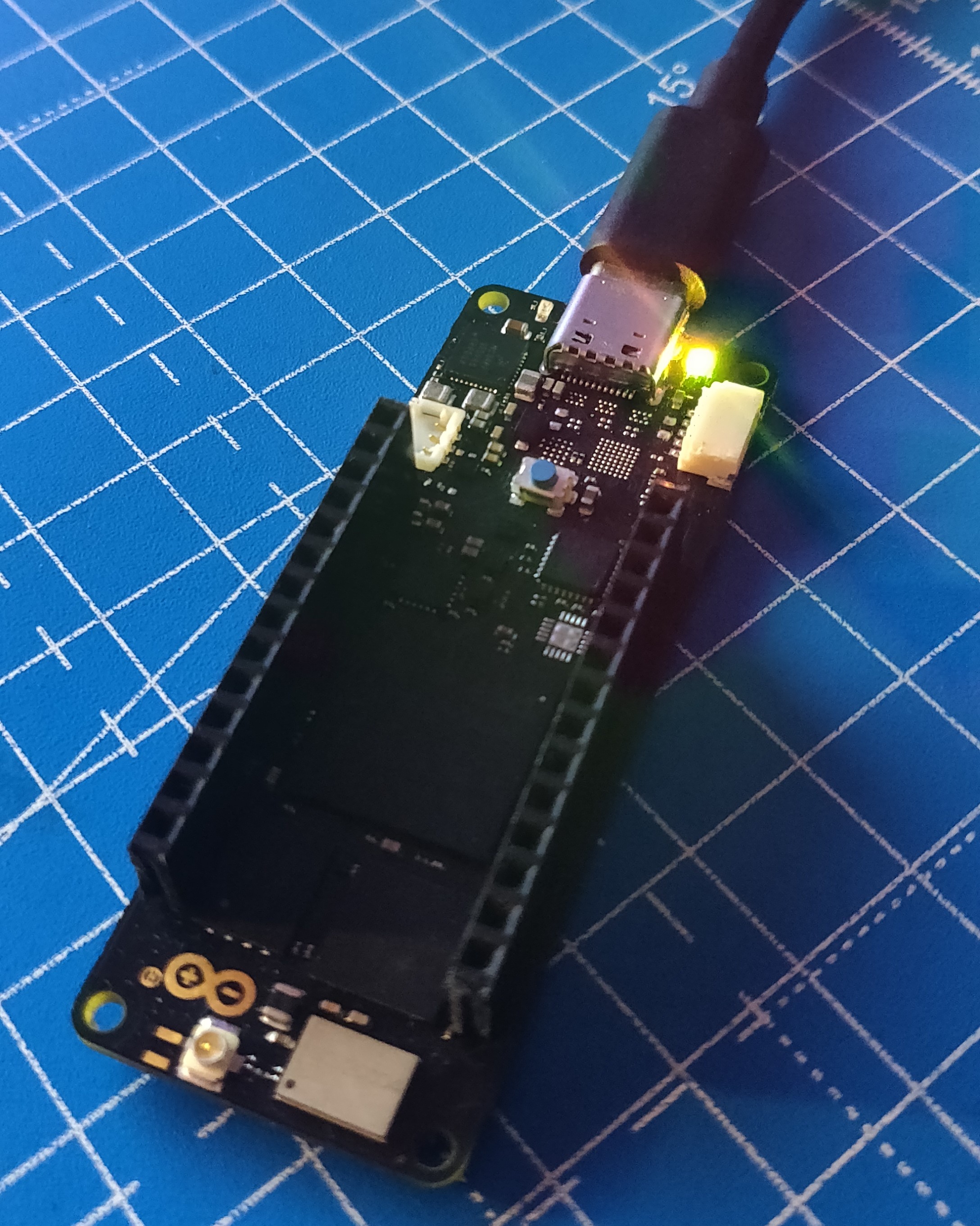
I first started with my Arduino Portenta H7 Lite Connected, a powerful dual-core microcontroller from the Arduino Pro range of devices. It has a really useful set of features alongside dual core operation such as Wifi/Bluetooth support, high density connectors under the board that allow a whole range of shields to be stacked, MKR compatible pinouts, and a LOT of wired communication interfaces such as I2C, Serial, CAN, SPI and Ethernet. The Lite Connected is a variant of the Portenta H7, with all the features except one secure element and no high-resolution video interface, which I don’t intend on using anyway. It has two cores - M7 and M4, where the M7 is the main core that can boots up by default, and can boot up the M4 core using the bootM4(); function in the setup of the user-defined M7 code. I tried running some of the examples from the micro_ros_arduino repository. I must point out, I did not follow any written tutorial (I actually did not find any) and I’ve tried to understand the examples only by looking at the code. Also, in the following examples, I additionally included the bootM4(); function call in the setup of the M7 code and uploaded a simple blink sketch (green LED) to the M4 core.
- Publisher example: Simple publisher that increments a timer periodically and publishes its integer value. Includes a error loop where the red LED flashes when a micro_ros_agent is not detected
- Subscriber example: Simple subscriber that subscribes to a Twist message and switches the red LED on or off based on its value. Also contains the error loop.
- Time Sync example: Synchronizes time with the micro_ros_agent and prints it to Serial1. Also contains the error loop.
- Reconnection example: Checks and decides the state of the micro_ros_agent, and it either increments a counter if the agent is connected or destroys the created entitites (like publisher, executor, timer) if the agent is disconnected.
- Service example: Simple service that requires two integer inputs, and returns the sum. Also contains the error loop.
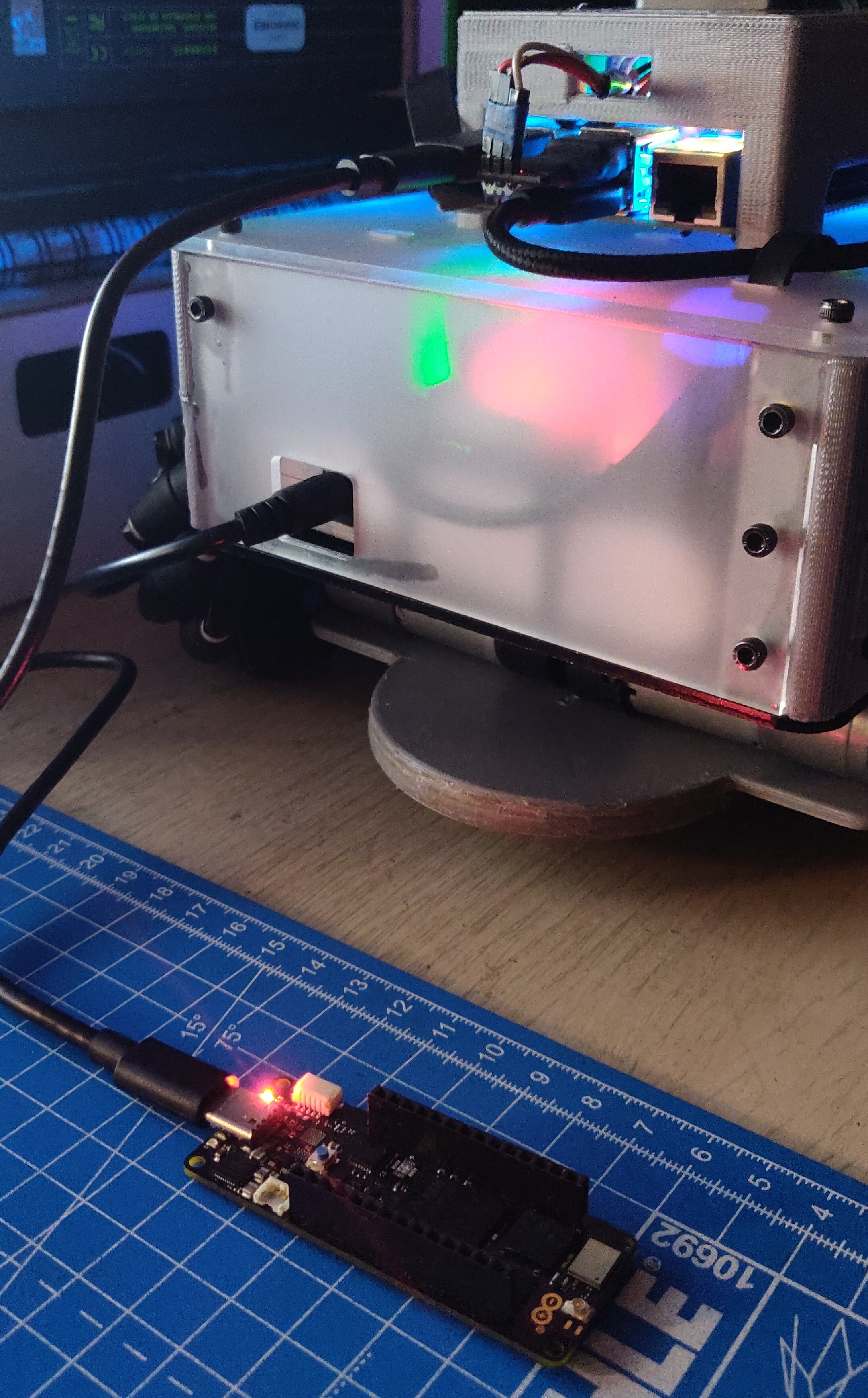
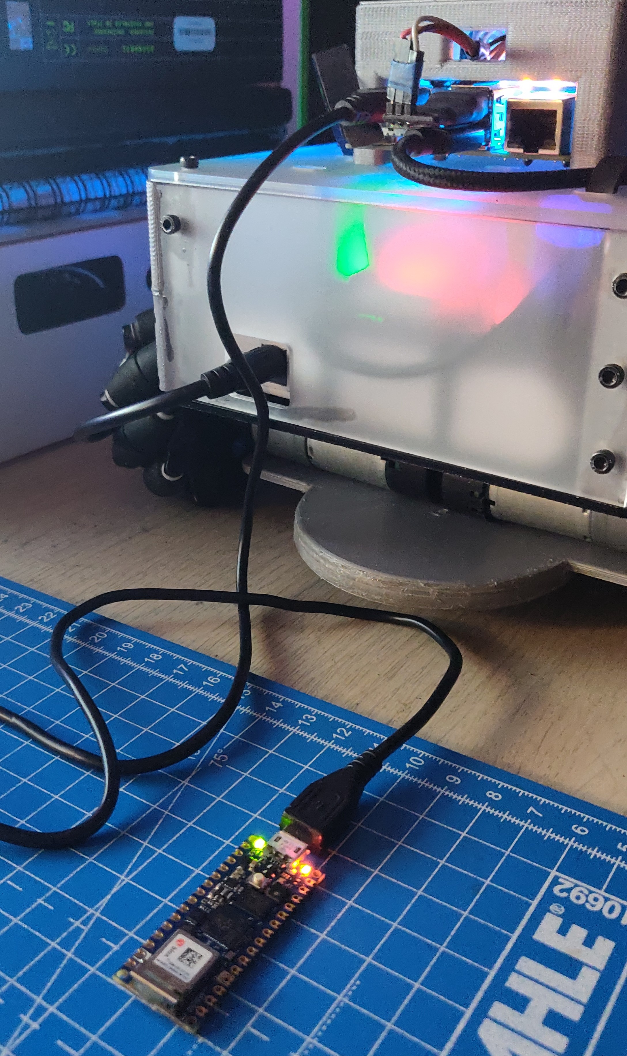
In the above examples, since I was unable to use WSL2, I decided to use the AKROS robot instead. Since I had already installed ROS2 Galactic on the robot computer, I could use it straight away. I first created a micro-ROS workspace and cloned the micro_ros_setup package. Now since I’m using precompiled libraries, I didn’t need to follow all the steps, and could instead directly create and build a micro-ROS agent as described in this tutorial here. Once the agent is created and built, I ran it using this command: ros2 run micro_ros_agent micro_ros_agent serial --dev /dev/ttyACM1 where /dev/ttyACM1 is the serial port of the microcontroller. Next, I simply uploaded the micro-ROS code to my Portenta using my laptop, and then plugged it to the Raspberry Pi 4 USB port and I was good to go. I was able to verify everything was working by using the ROS2 CLI tools using JupyterLab running on the RPi4. Few things I was unable to test - first, the Time Sync example. It prints its output to Serial1, which I was unable to access using JupyterLab. I am certain that it connects to ROS2 because it does not enter the error loop, but I need to use a GUI serial monitor when I next connect it to a screen. The second thing I was unable to test was the Service example because I was unable to get a response from the service. There seems to be some open and closed issues on the GitHub repository but I need some time to look into it and fix it. Other than these two, the other examples worked as expected and I was able to test them using my setup.
Eventually, I expect to use the Arduino Portenta with micro-ROS to interface with serial bus servo motors. Like I’ve talked about in an earlier post, the Dyanmixel MKR shield fits perfectly on top of the Arduino Portenta and works quite well (without micro-ROS for now). I also intend on interfacing it with the STS3215 servo motors that I also purchased a while ago. The reason I wanted to test the dual-core behavior by adding the bootM4(); function call, is because I intend to implement the main ROS functionality in the M7 core and some features in the M4 core, and communicate between them asynchronously using remote procedure calls.
Arduino Nano RP2040 Connect (Serial Transport)
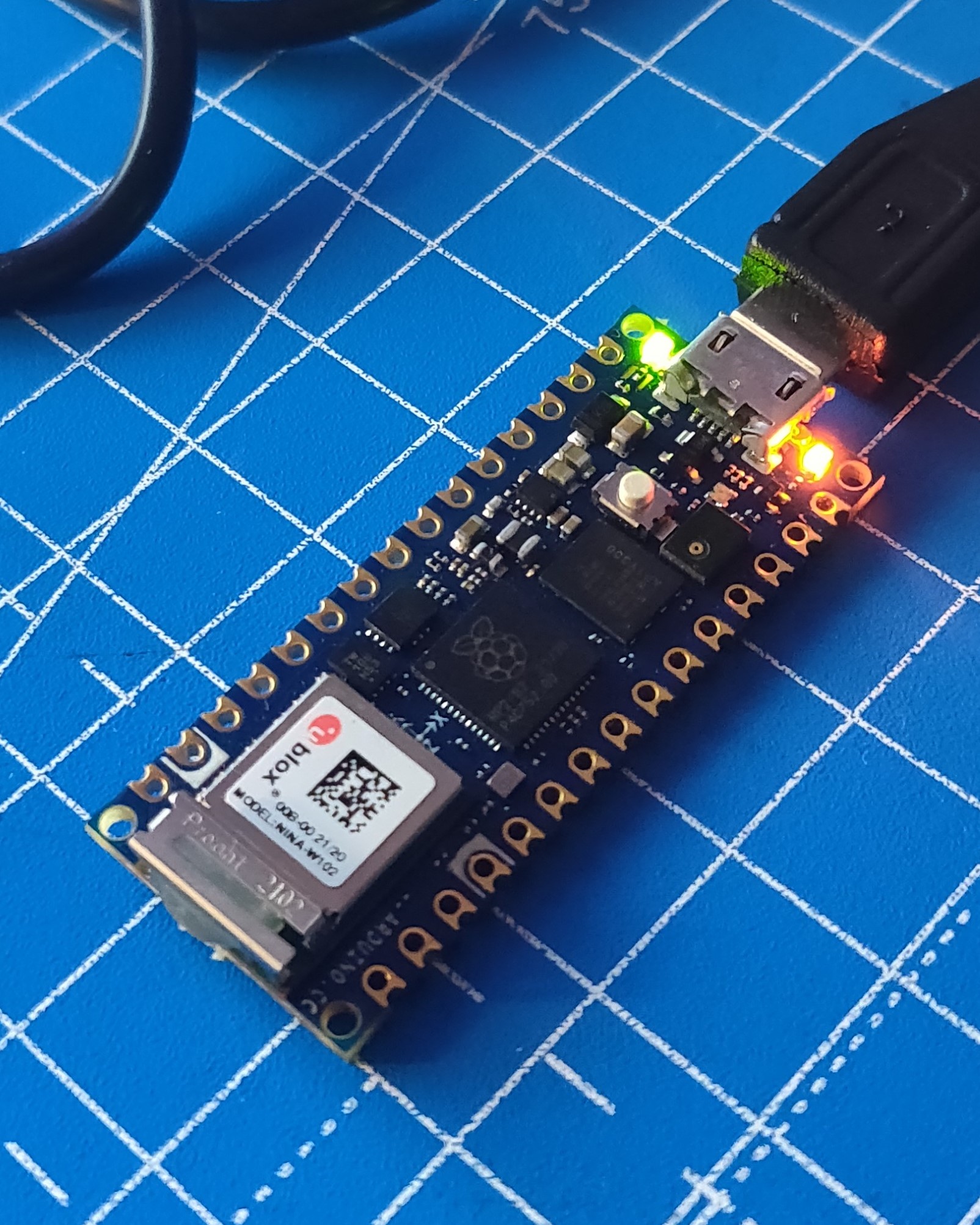
Next, I decided to try the same examples with my new Arduino Nano RP2040 Connect. This device includes the RP2040 chip from Raspberry Pi along with an ESP32 based wifi module on one really small board. It also has a 6 axis IMU, a MEMS microphone all the spare GPIO are exposed to the user. It is a really neat board (and reasonably priced at about 25 Euros), and is one of the boards I’m considering for my next build which is a miniature version of the AKROS robot running micro-ROS. This board however uses a different and a much more constrained configuration than the Arduino Portenta, while using the same libraries. While the Portenta uses colcon.meta which allows 10 publishers, 5 subscribers and 1 service, the Nano RP2040 uses colcon_verylowmem.meta and allows only 2 publishers and 1 subscriber.
So the Service example cannot be replicated on the Nano RP2040. The Time Sync example again could not be tested for the same reason as above. The Subscriber example and the Reconnection example were replicated as is and worked as expected, and was validated using the same workflow as before. For the Publisher example, I decided to try some different examples provided in by micro_ros_arduino:
- Decibel Publisher Example: Uses the onboard microphone and publishes the measured decibel level. Includes the error loop as described above.
- IMU ML Example: Uses the onboard IMU and a ML model (I don’t have any more details on this part, since I only went through the code and did not find any written tutorial) to detect if the person is walking, running, driving or stationary. It also counts the steps taken. Both the number of steps and the detection are published to separate topics. Also includes the error loop.
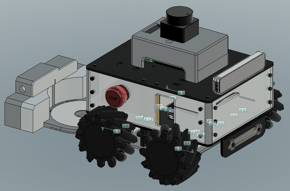
Once again I used the same workflow as with the Arduino Portenta. I only had to change the board type in the Arduino IDE. The only issue I faced was with the Decibel Publisher example. While the publisher worked and the code seems to be correct, the published value was a static number. Either I am not initializing the microphone correctly or the device itself has malfunctioned, I cannot say for sure. I need to investigate this further. I initially purchased the Nano RP2040 to compare it with the RPi Pico and the ESP32 boards, and make a final decision on what to use for my next project. But after the last few days, I think I’ve already made my decision without testing the other two boards. My goal is to build a miniature version of my AKROS robot using micro-ROS, and the Nano RP2040 definitely seems perfect - One, it has a good number of much needed GPIO for all the motors, encoders and sensors. Secondly, the on-board IMU is definitely a bonus and means that I dont have to add one separately. Finally, the micro-ROS configuration for the Nano RP2040 is quite sufficient for my application.
RPi Pico RP2040 (Serial Transport)
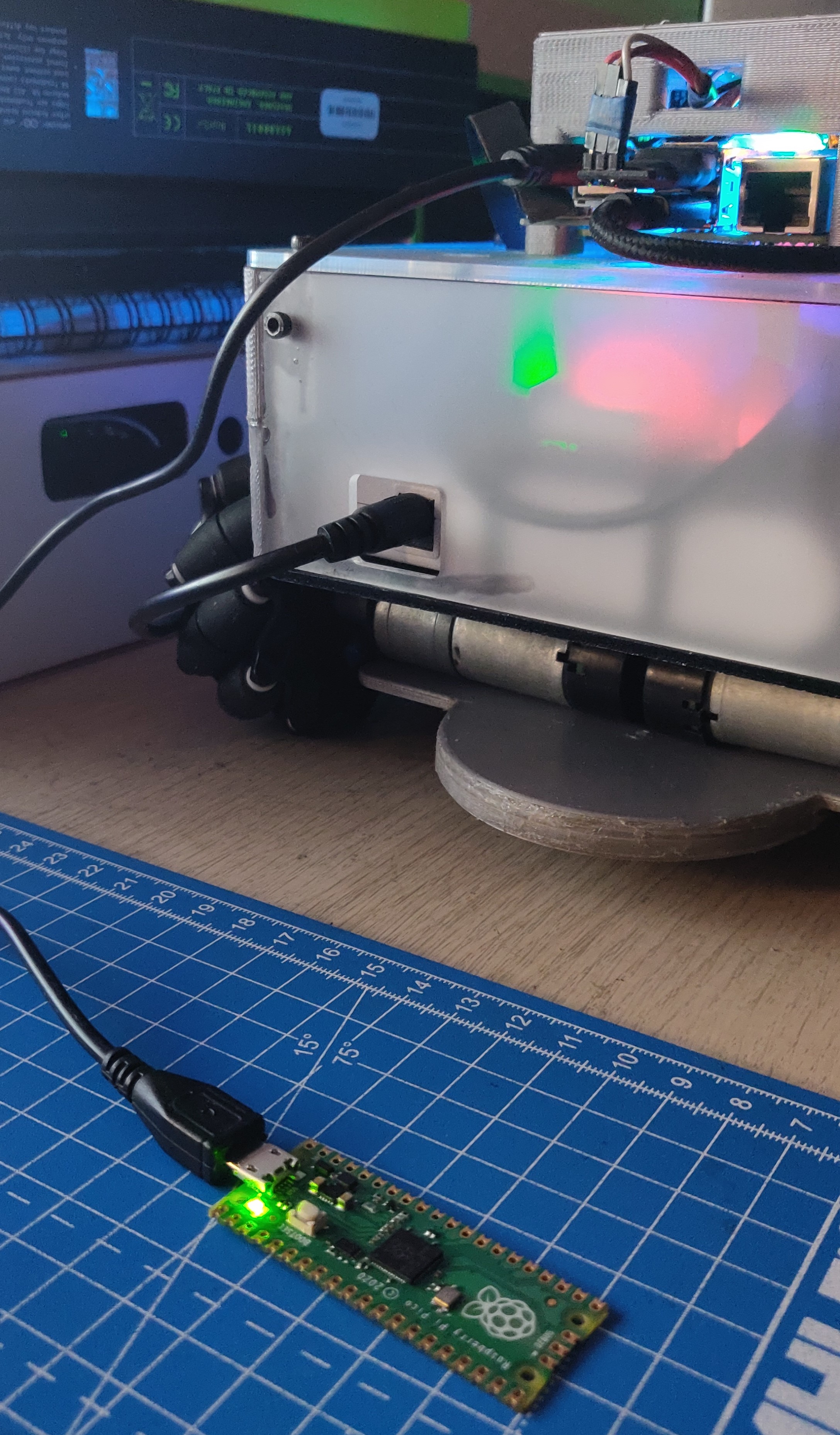
Despite having already chosen the Nano RP2040, I also decided to try out the RPi Pico board mainly because it does not use the Arduino IDE and the precompiled libraries in micro_ros_arduino. It instead uses the micro_ros_raspberrypi_pico_sdk, which once built, generates a .uf2 file which needs to be copied into the device. But since the Arduino IDE is not used, the workflow is different. As explained before, I cannot use platformIO on Windows because micro-ROS cannot compile and the precompiled libraries do not work. So, I decided to use WSL2, which works because the code is not flashed to the device via USB but instead the .uf2 file is copied. So, now I am able to create the file using platformIO with WSL2 and the steps mentioned here, then I can copy it to Windows and to the drive created by the RPi Pico. And it works! I only tried the sample code provided in the repository, which is the same Publisher example I tried out with the Portenta, but written in C.
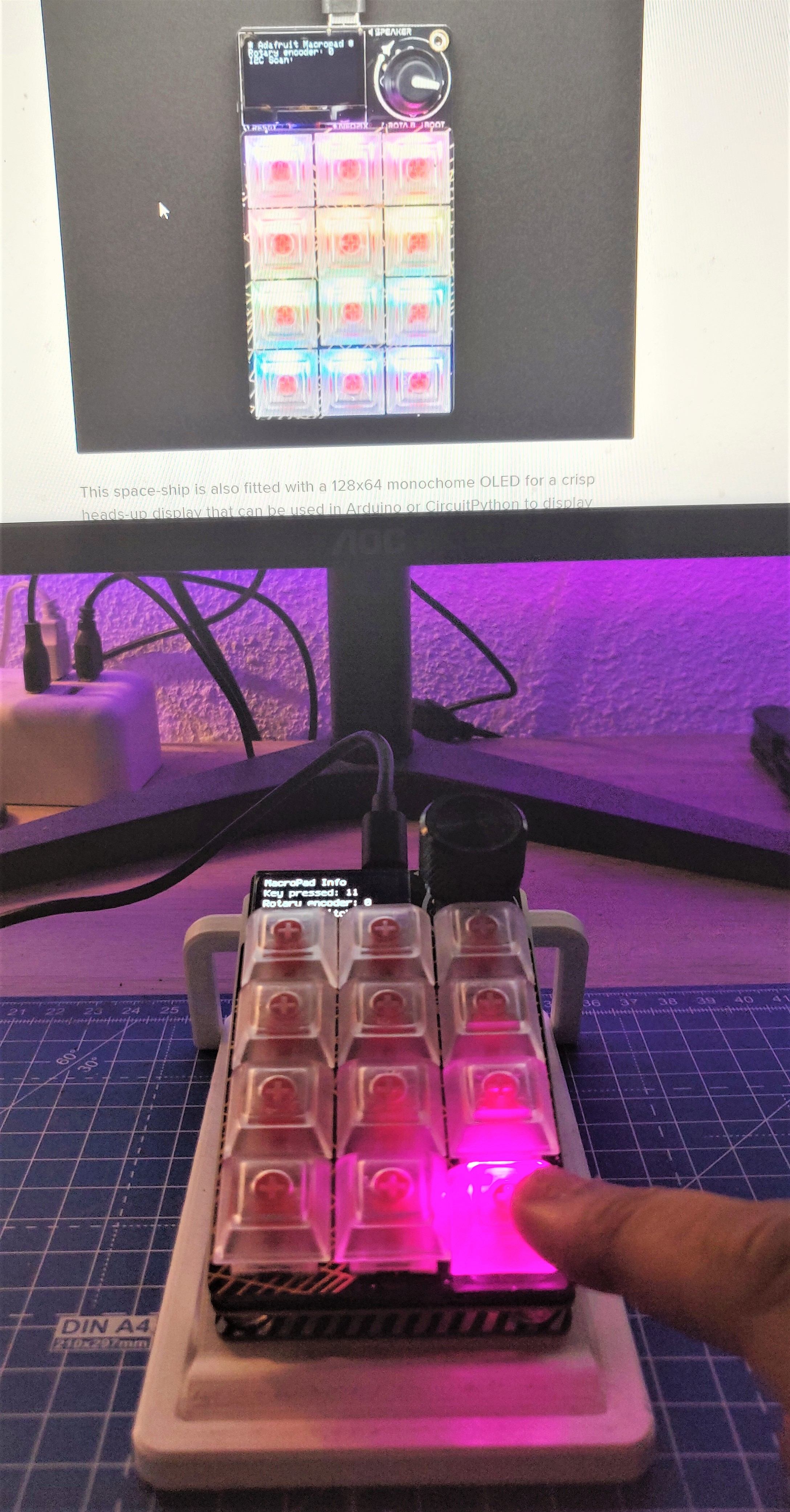
In my previous post I showed a picture of the Adafruit Macropad RP2040, which also has the same chip and uses the same way of uploading code using .uf2 files. I intend to try and run micro-ROS on it, and potentially use the device as a Twist publisher, since I normally use a numpad and I don’t have a keyboard with one anymore.
Next Steps
For my next steps with micro-ROS, I first want to spend some time fixing the Service example with the Portenta board, and the Decibel example from the Nano RP2040. Next, I want to explore different transport methods - UDP over Ethernet using the Portenta (with the Portenta Breakout Board), and UDP over Wifi for both the Portenta and the Nano RP2040. Once these are done, I want to try the same things with Teensy 4.1 - with the Serial and UDP over Ethernet transports. I am using the Teensy 4.1 with ROSSerial and I intend to use micro-ROS when I port the rest of the software stack to ROS2. Finally, when all this is done, or if I get bored, I will try and set up a simple micro-ROS example with the Adafruit Macropad RP2040.
Meanwhile with my robots, I have also made some progress which I plan on continuing: For the AKROS robot, I have updated the udev rules with symbolic links for each specific microcontroller that I plan on experimenting with or implementing. So, now I do not need to search /dev/tty* and see which port corresponds to which device. The udev rules look like this:
KERNEL=="ttyACM*", ATTRS{idProduct}=="0483", SYMLINK+="ttyUSB_TEENSY"
KERNEL=="ttyACM*", ATTRS{idProduct}=="025b", SYMLINK+="ttyUSB_PORTENTA"
KERNEL=="ttyACM*", ATTRS{idProduct}=="005e", SYMLINK+="ttyUSB_NANO_RP2040"
KERNEL=="ttyACM*", ATTRS{idProduct}=="000a", SYMLINK+="ttyUSB_RPI_PICO"
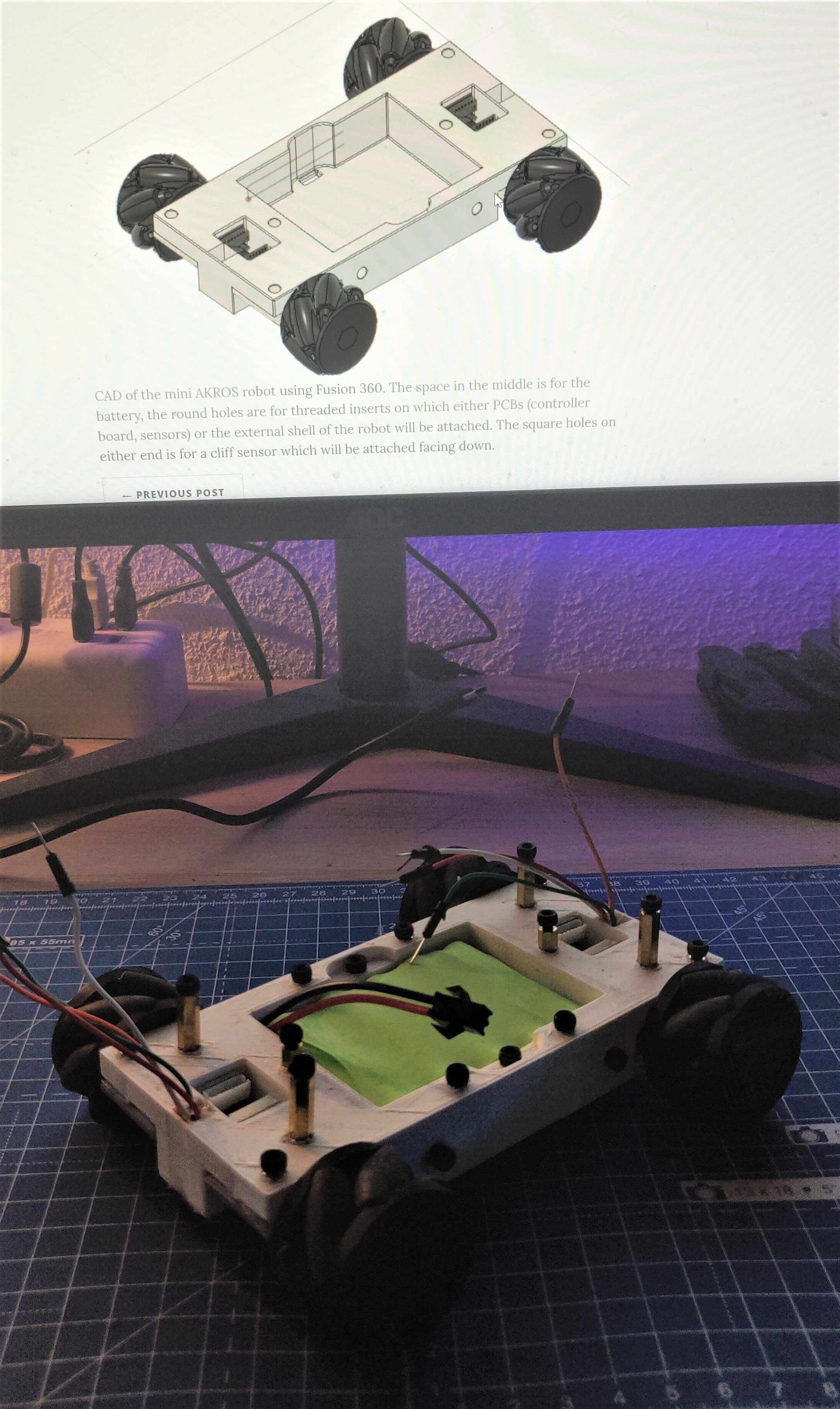
In terms of the chassis, I have ordered a few new parts - opaque and matte black acrylic plates for the robot. I needed to update the template and also block some light from the LEDs in the base module. Also, since there won’t be any more hardware changes between AKROS and AKROS2, a different look would be nice. As I explained in my last post, I am also designing a miniature version of the AKROS robot. Last time, I was still thinking about which microcontroller to use. I think by now I am certain it will be the Arduino Nano RP2040 Connect. So, I can continue with the PCB design for the motor controller. Since the last time, I also 3D printed the prototype that I had designed, and gone through one design iteration after identifying some issues.
For next week, I want to explore the UDP transport with the Portenta and the Nano RP2040. Meanwhile, I expect to receive the acrylic parts and hopefully I also get the chance to visit the office use the 3D printer.