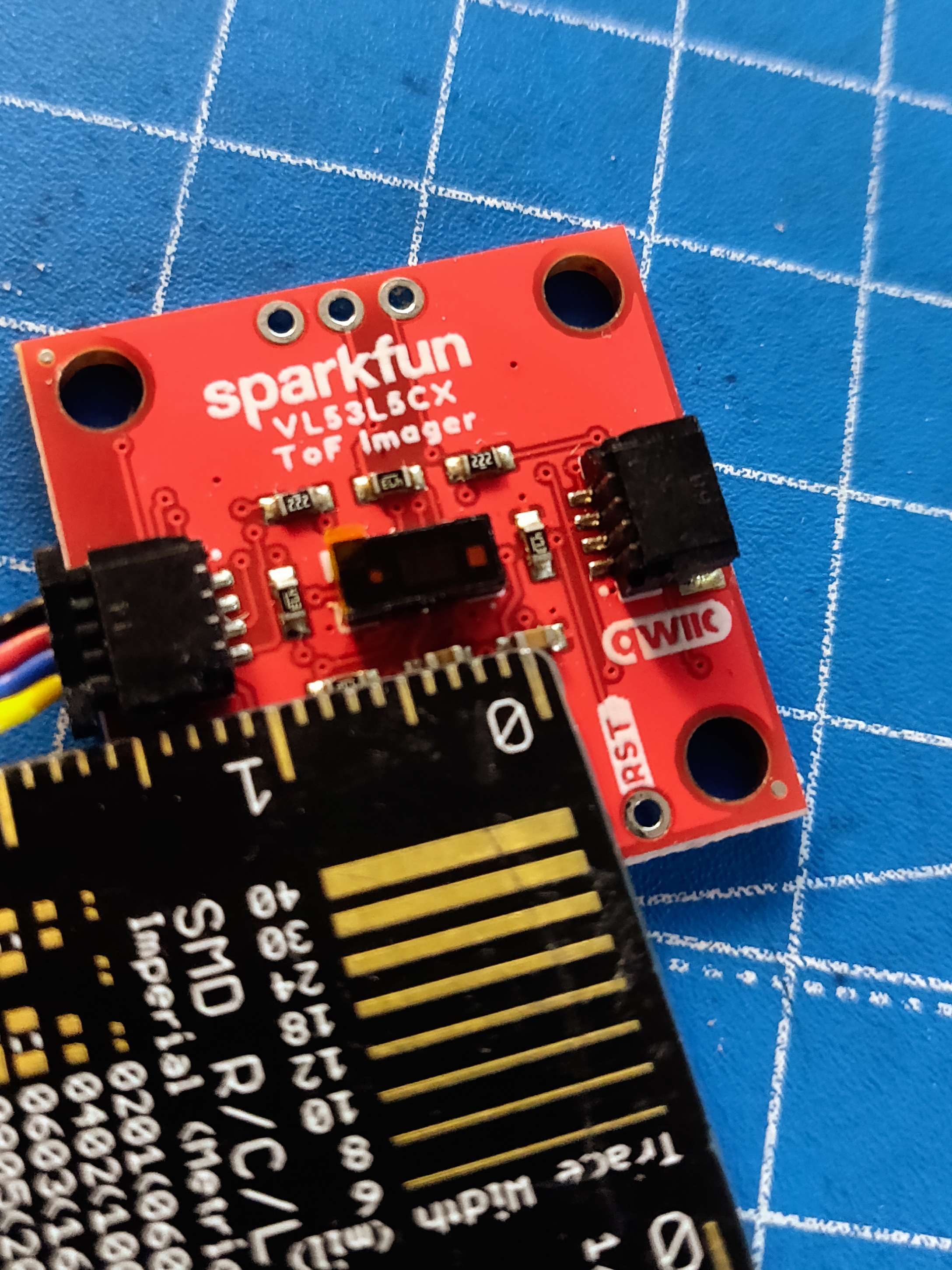
This week, I received some of the goodies I mentioned in the last update. One of them (I’ll talk about the other later) was the Sparkfun Qwiic ToF Imager based on the VL53L5CX sensor by STMicroelectronics. It is a 8x8 time-of-flight (ToF) sensor (64 pixels), with a field-of-view of 45 degrees and a maximum range of 4 meters. It provides data on an I2C bus, at 15Hz for an 8x8 grid, and 60Hz for 4x4. The sensor also comes with additional features such as power modes and motion/reflectance indicators which allow it to detect glass up to 60cm. Since it uses I2C, multiple sensors can be linked to the same bus, which makes it an ideal sensor for robotics applications. More documentation can be found here and here. I immediately decided to start playing with it, and also decided to use it as an opportunity to implement a micro-ROS application from scratch.
First, I started off by installing the Sparkfun VL53L5CX library on the Arduino IDE and then loaded the some example sketches. Most of the examples use only the ToF capabilities, and result in a 8x8 ordered array of measured data, captured at 15Hz. This data is also formatted and written to the serial port. One of the examples also comes with an accompanying Processing app that visualizes the data points written to the serial port. Finally, after playing around with some settings, I ended up with a final Arduino + Processing example that configures, initializes and polls the sensor, and the resulting depth map is visualized by Processing.

micro-ROS Pointcloud Publisher
The next step was to make a micro-ROS node. Since, I am using pre-compiled micro-ROS (micro_ros_arduino v2.0.5-galactic) libraries, I decided not to make a custom message type (for now) and instead use the PointCloud2 (PCL2) message type, which is most commonly used with such sensors. Now, since the PCL2 message is huge in size, I decided to use devices that can handle the size (and speed) requirements. So, I decided to skip the RP2040 based devices, and chose the Arduino Portenta. I also have a Teensy 4.1 which should also support the communication of this message type, but I couldn’t use it as I will explain later. First, I used the Integer Publisher example from micro_ros_arduino, and added the VL53L5CX code from my earlier experiment. Since, we publish a PCL2 message, I had to change the publisher, so that it publishes a PointCloud2 instead of UInt32. Since the PCL2 message is a complex, and dynamic message type, I also had to initialize the memory for this message, for which I used the Types Handling example from last week.
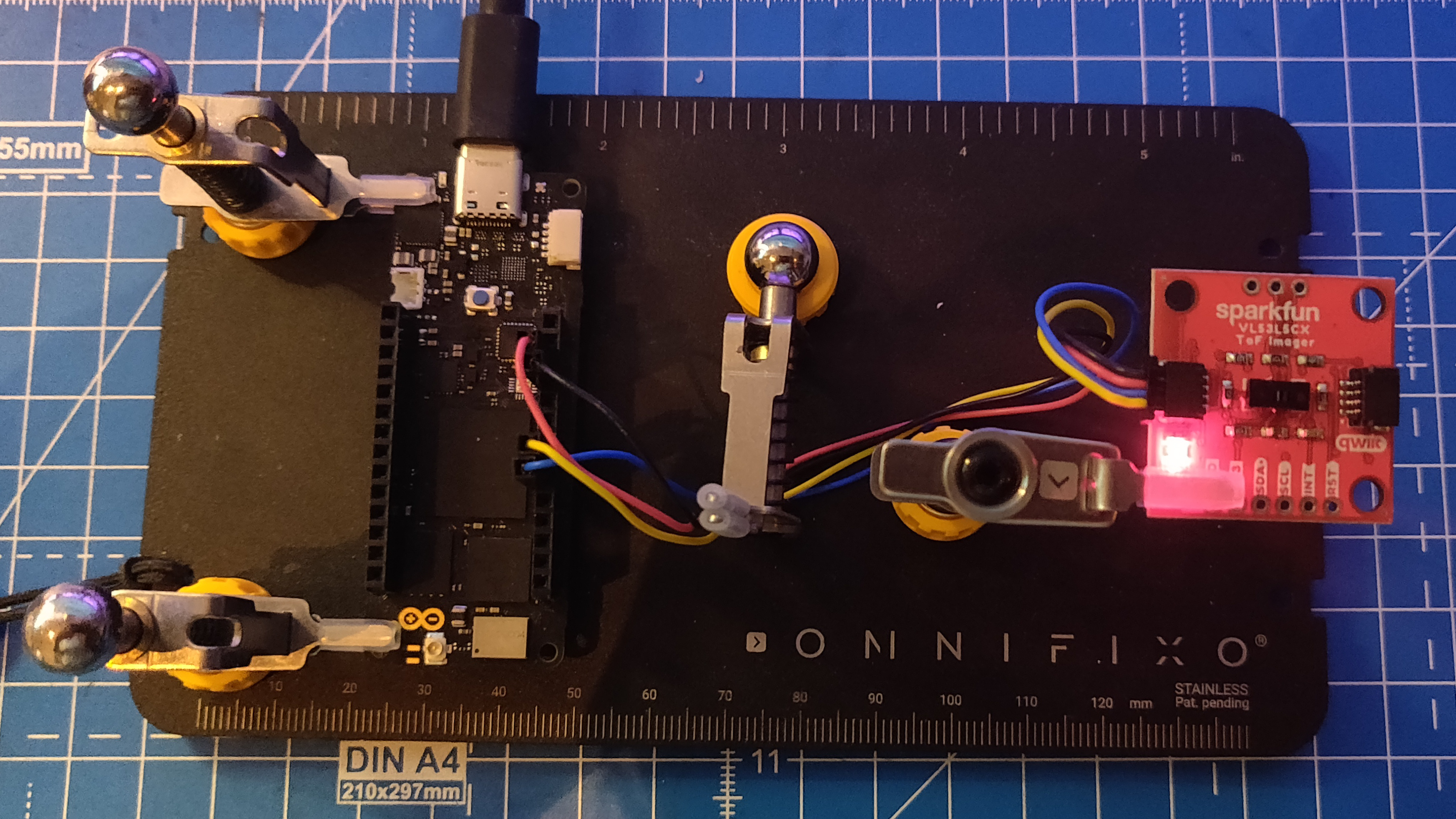
Now, since the PCL library is not available on the Arduino, I couldn’t use any of its utility functions to create a modifier and iterators to populate the message. This method is shown using ROS2 in this video by the Polyhobbyist and the code can be found https://github.com/polyhobbyist/ros_qwiic_tof. Since I am using micro-ROS, I instead had to computate and populate the message data myself. Here’s how I did it: In the Integer Publisher example, the setup function defines an allocator, a node, a publisher, a timer and an executor using the ROS2 Client Support Library (rcl) and the ROS2 Client Library package for C (rclc). The loop function is just two lines - the function call to spin the executor and a small delay before the next loop. So, every time period, the executor is spun, which updates the timer, and the message is published from within the timer callback. Since I need to poll the sensor and populate the PCL2 message at every time instance, I couldn’t add all of this to the timer callback since it needs to be as quick as possible. Instead, I removed the timer and executor all together, and added the publisher function call directly at the end of the loop function. Now, in the setup function, I initialize the micro-ROS entities like before, and then initialize the message memory and fill in the static fields in the PCL2 message.
In the loop function, I first poll the sensor, compute the position of each sensor measurement (detection), and populate the dynamic fields of the PCL2 message. There were a few considerations to be made here - first the data from the sensor is an ordered array of Float32 values, with only depth measurements for each point on the 8x8 grid. First the position of each detection needs to be computed in the sensor’s frame of reference. This can be done with some simple trigonometry, and results in x, y and z values for each detection on the grid. Next, since the data struct within the PCL2 message is a 1-dimensional array of type UInt8, the calculated position values (Float32, 4 bytes) need to be decomposed into four UInt8 values (1 byte each) and then appended to the array. (Note: The calculated position values range between 0 and 4 meters, and if stored as integers in mm, the maximum value for each data point is 4000. This can fit in a UInt16 variable (2 bytes) instead of Float32, but apparently RViz2 needs PointCloud2 messages to be of Float32 type as seen in this forum question, and this source code.)
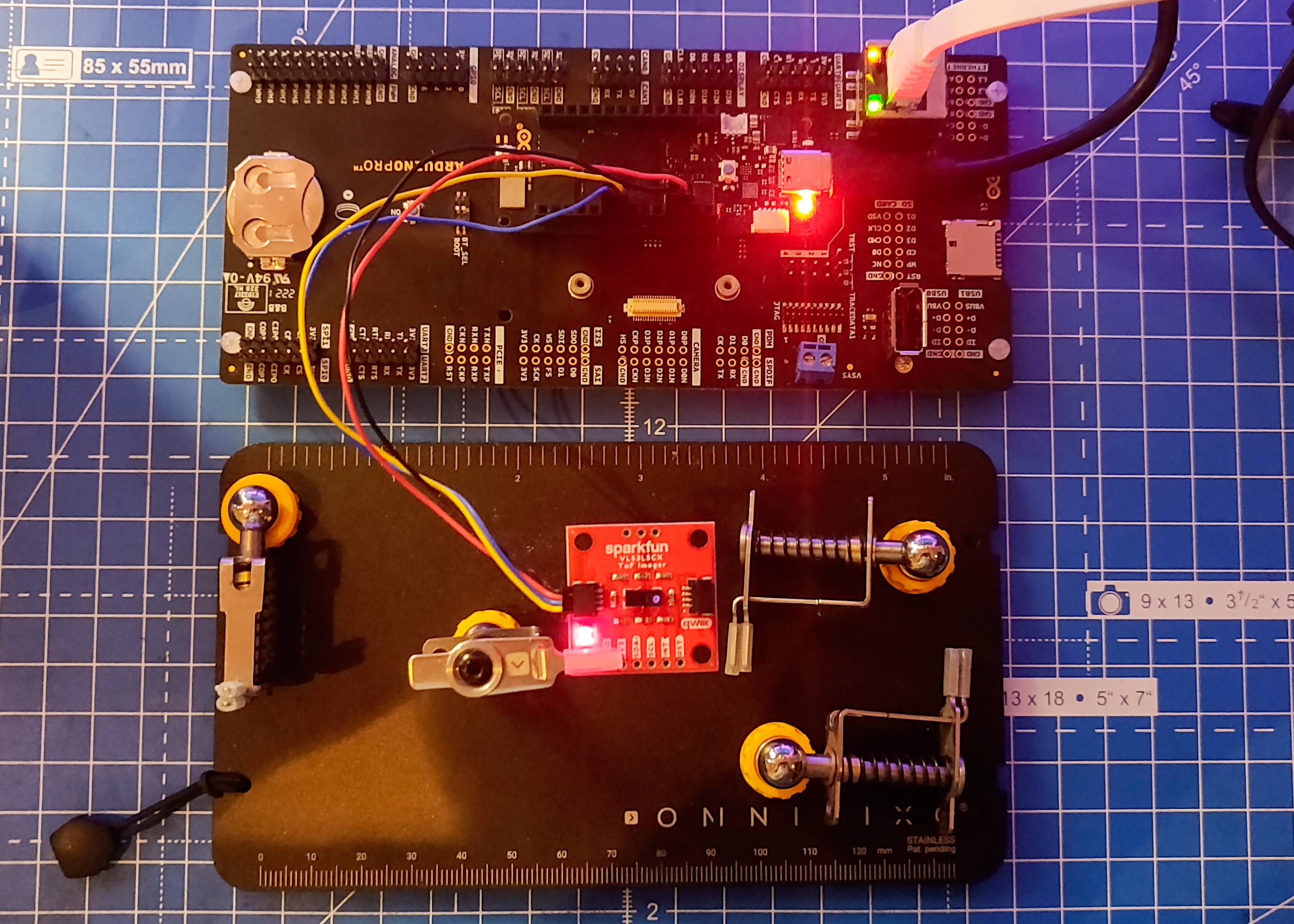
Now, only one field remains - the timestamp. For this, I used the Time Sync example to synchronize the time between the micro-ROS agent on the ROS2 side and the client on the Portenta. This is done in the loop function at every time period, and the resulting timestamp is then filled into the corresponding field in the header of the PCL2 message. Now, the message is populated and ready to be published. Once I was satisfied with the code, the next step was to test it with different transports using the RPi4 on the AKROS robot.
I decided to skip TCP and focus on only the transports I had tried so far - Serial and UDP over WiFi and Ethernet (using the Portenta Breakout board). Unfortunately, only the ethernet transport worked. For the other two, while the serial transport put Portenta in the error loop after working momentarily, the WiFi transport failed to even connect to the agent. At first I thought I had fried the WiFi chip on the Portenta, but I retried it with another example and it worked. I think the message size is too big and the WiFi and serial transports cannot handle it. It could also not work because of the removal of the timer and the executor. I will investigate this further when I have the time, but for the time being, I decided to continue with the UDP over Ethernet transport, as described in the last update.
Visualization
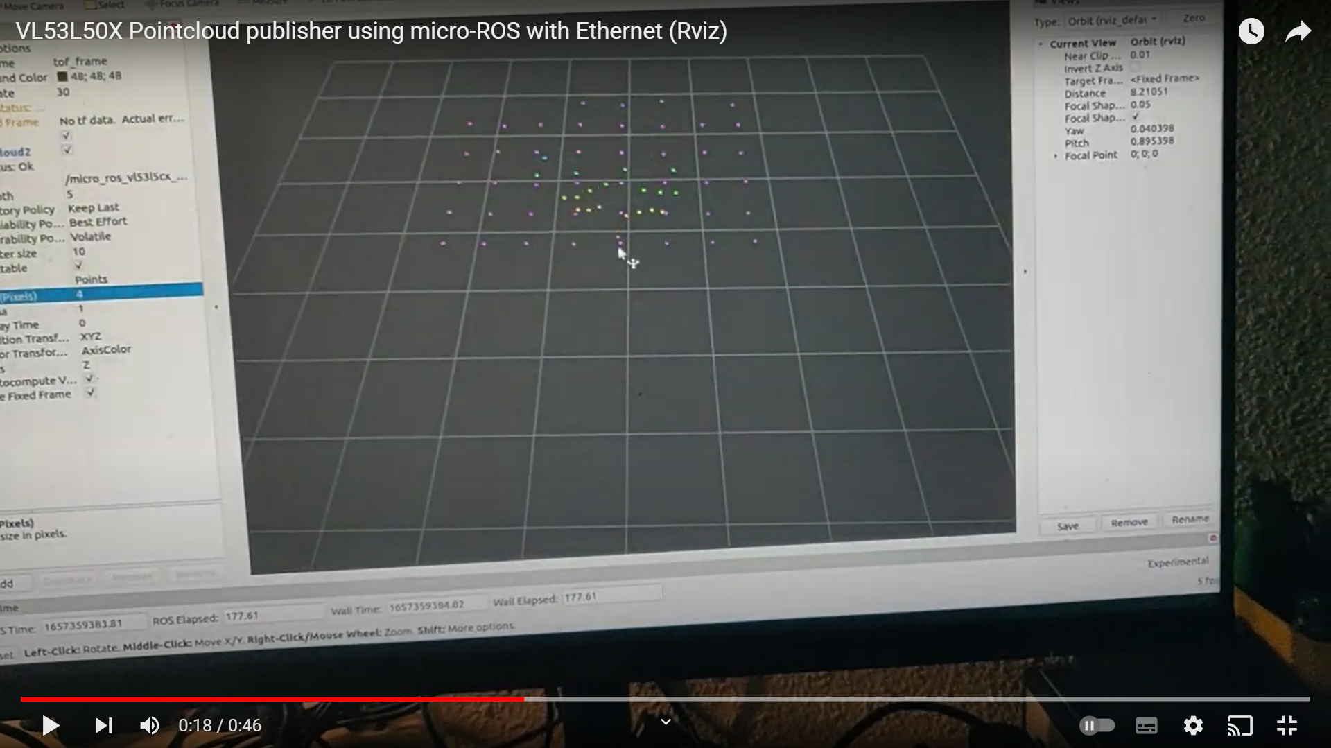
Next, I wanted to visualize the sensor data. First, I decided to try with RViz2 - I launched the agent from my RPi4, then launched RViz and was immediately able to add and visualize the published PointCloud2. But this method is not only inconvenient since I need to connect the RPi to a screen, but also quite slow. Another method is to launch RViz2 from a different ROS2 PC over the same network, so I decided to the ROS2 installation I have on WSL2. Unlike WSL1, WSL2 keeps its WLAN IP address hidden and it is not easily possible to access devices connected to the Windows 10 host. So, I decided to try and fix my Foxglove Studio setup, which on my first try few months ago, did not work with ROS2.
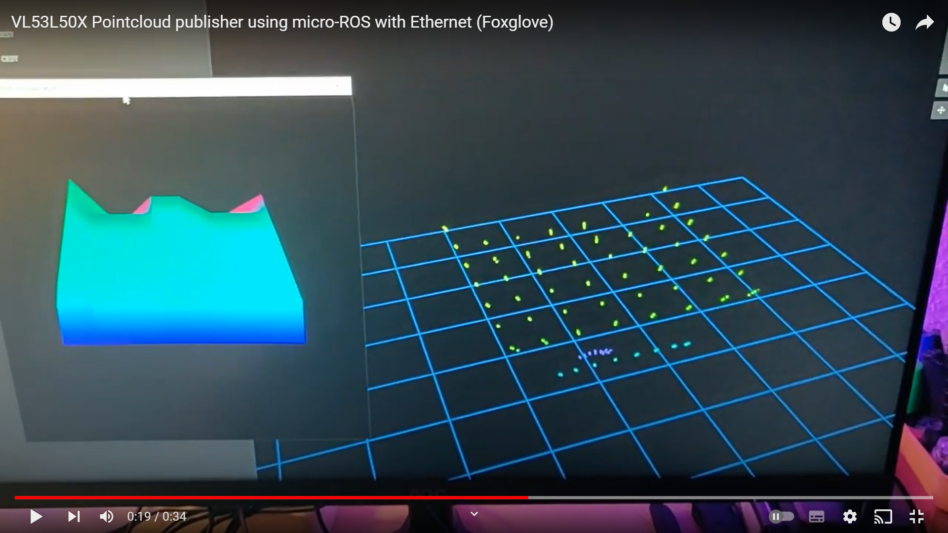
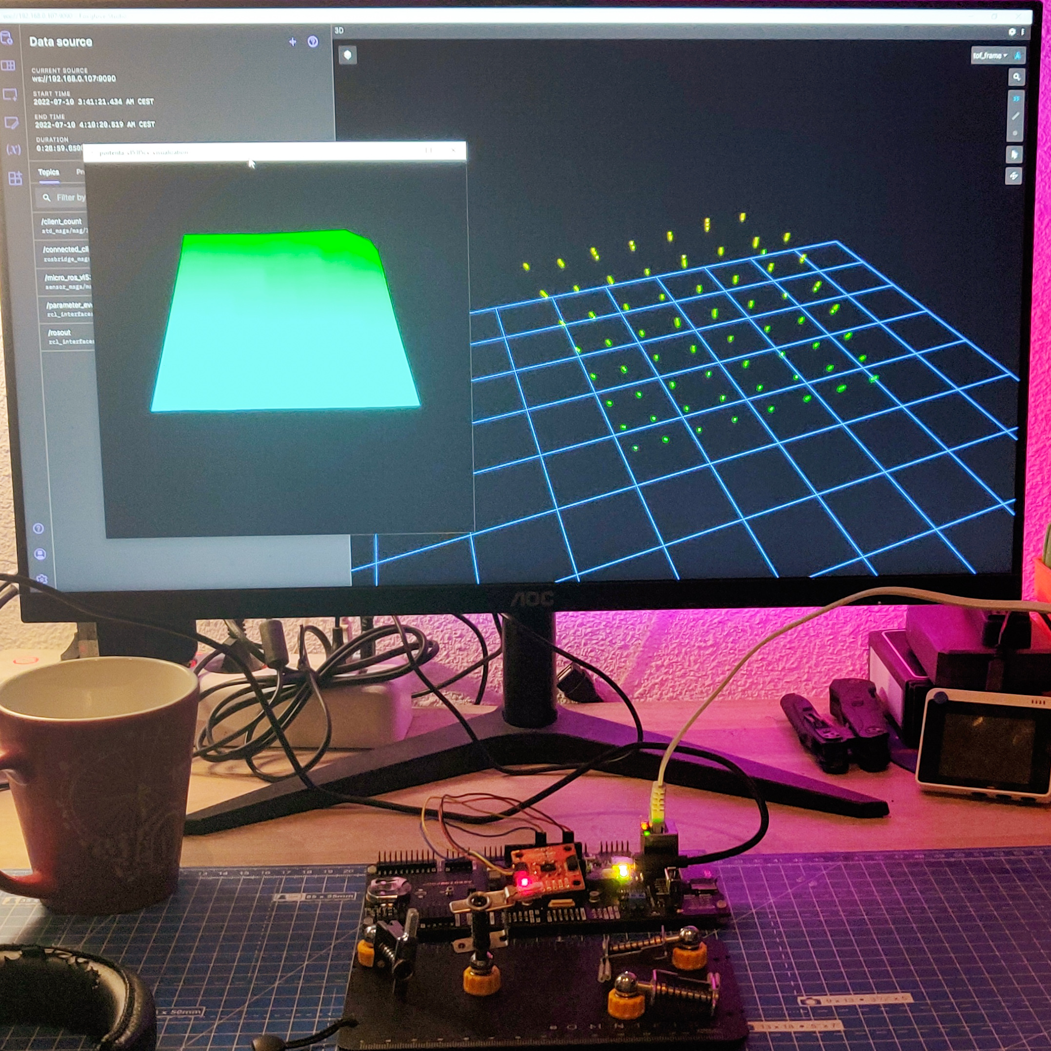
Foxglove is one of my favourite ROS tools when working on Windows. It allows me to open an app from the start menu, and visualize data streamed to/from my linux based ROS computers. I can do this without any complicated and time consuming setup. For ROS1, it connects to the rosmaster by setting the ROS_MASTER_URI and ROS_HOSTNAME environment variables on the RPi (as explained here), and then it is defined in Foxglove on Windows. For ROS2, all the devices that talk on a network must be configured with the same ROS_DOMAIN_ID, as explained here. Once again, this is an evironment variable that needs to be set on the RPi, and this needs to be defined in Foxglove. But this did not work either, I think that it is not just the environment variable, ROS2 also needs to be installed on Windows 10 for this to work. But maybe I’m wrong, I need to investigate this. Fortunately, Foxglove also has a few other alternatives - one of them being the ROSBridge Suite, which works on both ROS and ROS2. As explained here, I installed rosbridge_suite on my RPi (I did it for both Noetic and Galactic, so I can use it for ROS1 as well), and ran the corresponding launch file on ROS2 which opens up a ROSBridge server. This lets networked computers access messages by simply connecting to the port of the ROSBridge server. This connection on the other hand was instant, and very reliable with quite low latency as seen in the video below:
Other micro-ROS Changes
I also tried a few other things that are not functionally relevant but nice to have. First, I updated the ROS_DOMAIN_ID, which is set to 0 by default. On the RPi, it is quite easy, and is done by simply updating the environment variable. On the micro-ROS client side, it is not so straightforward. As explained in the micro-ROS rcl/rclc tutorials, an init_options variable needs to be defined and then it is added to the initialization support using this function call: rclc_support_init_with_options(&support, 0, NULL, &init_options, &allocator) instead of rclc_support_init(&support, 0, NULL, &allocator). This is the recommended method for ROS2 Galactic and beyond, for ROS2 Foxy and earlier, there is a different method. With this working, I updated the bootup script to set the new ROS_DOMAIN_ID when the RPi boots up.
Next, I tried some additional examples. First, I decided to try the Reconnection example with the ethernet transport. Just like last week, it still did not work, but I was also unable to figure out the issue or find a fix. So, I opened an issue on the micro_ros_arduino repo explaining my analysis of the issue. Finally, I decided to go through the advanced micro-ROS tutorials. All of them are easy to understand and replicate, but to implement most of them I need to rebuild the micro-ROS libraries. I decided to leave them for a later time, and decided to spend some time working on the AKROS2 robot.
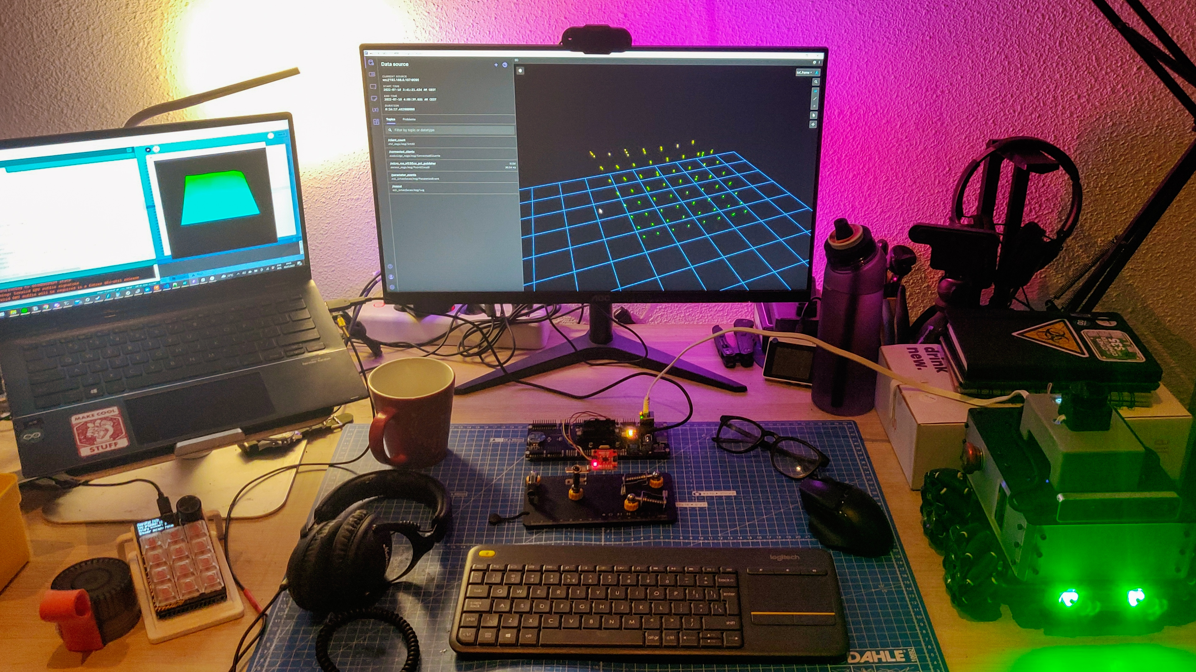
Update: I also had another open issue there, for the failing ethernet transport on the Teensy 4.1. Turns out the ethernet transport was simply added by a contributor and not tested officially. So it could have been an issue with the example or micro-ROS libraries, and not just the hardware. Fortunately, I found the root cause and the solution in the PJRC forums - the Teensy 4.1 ships with a pre-determined MAC address, so assigning it is not correct, and needs to be retrieved from internal memory. The following function retrieves the MAC address and stores it into an array of 6 bytes. I tested it out, and once it worked, made a pull request with the updated Ethernet publisher example. It is just been merged, so it could be found directly in the micro_ros_arduino repository. Now that Teensy 4.1 Ethernet is working, I can continue working on the AKROS2 robot.
AKROS(2) Updates
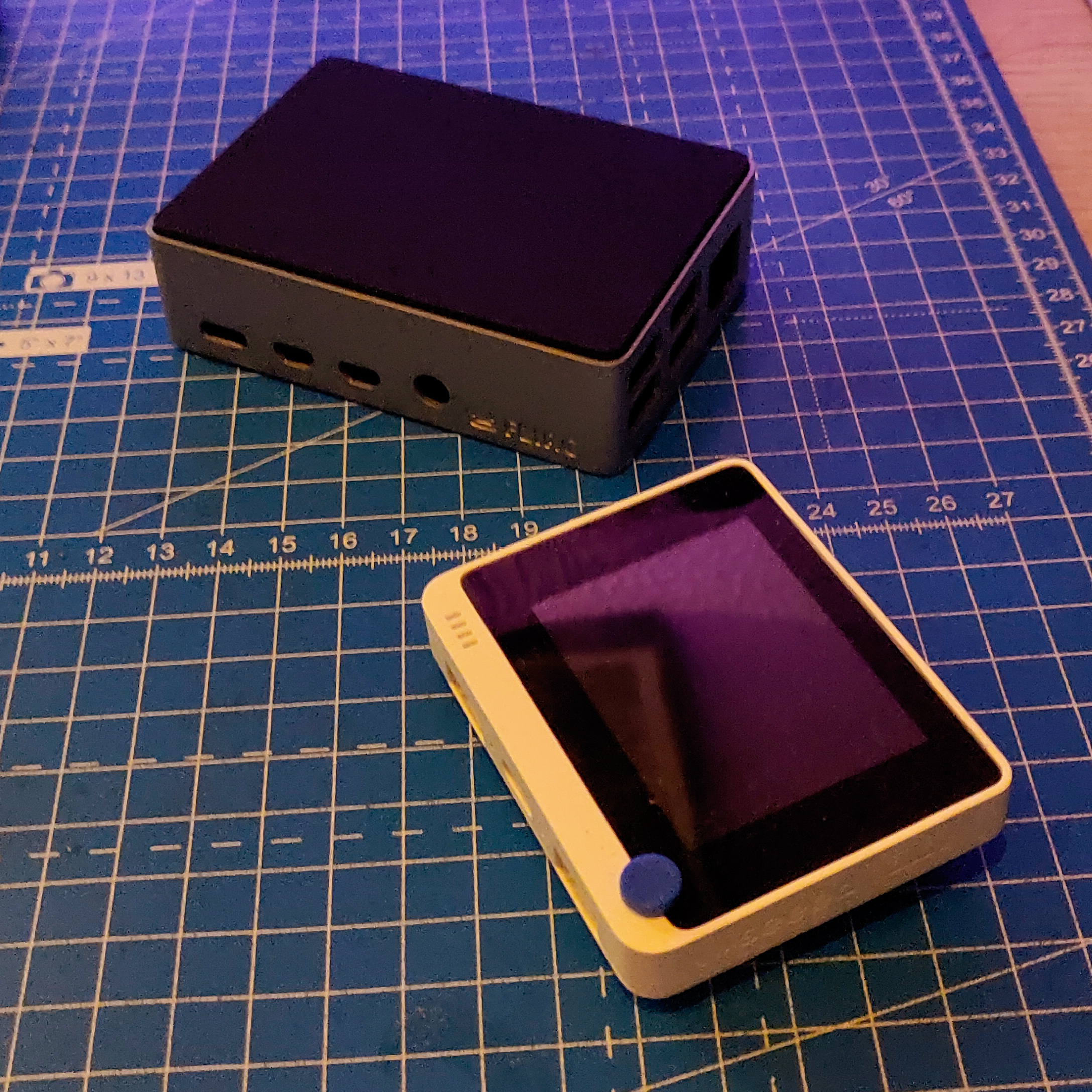
Like I mentioned in the last update, I found a way of making the robot more compact, while the laser scanner is still placed high enough for the beams not be obstructed by any part of the chassis. I only worked on the navigation module and the top base plate for now and the results look quite slick. I also decided to replace the 3D printed RPi case/cover with a Flirc case for RPi4, which uses its aluminium housing as a heat sink, and saves the space needed for a fan. It also looks really neat. The images below shows the new and old designs. I will try to 3D print and laser cut these new parts when I get the chance, but for now I intend to try out PCBWay’s 3D printing service when I place some PCB orders in the near future. While updating the 3D files, the URDF of the robot also needs to be updated with the new meshes. While normally, I do it using an external monitor connected to the RPi, but I learnt of a much simpler version in this week’s ROS news.
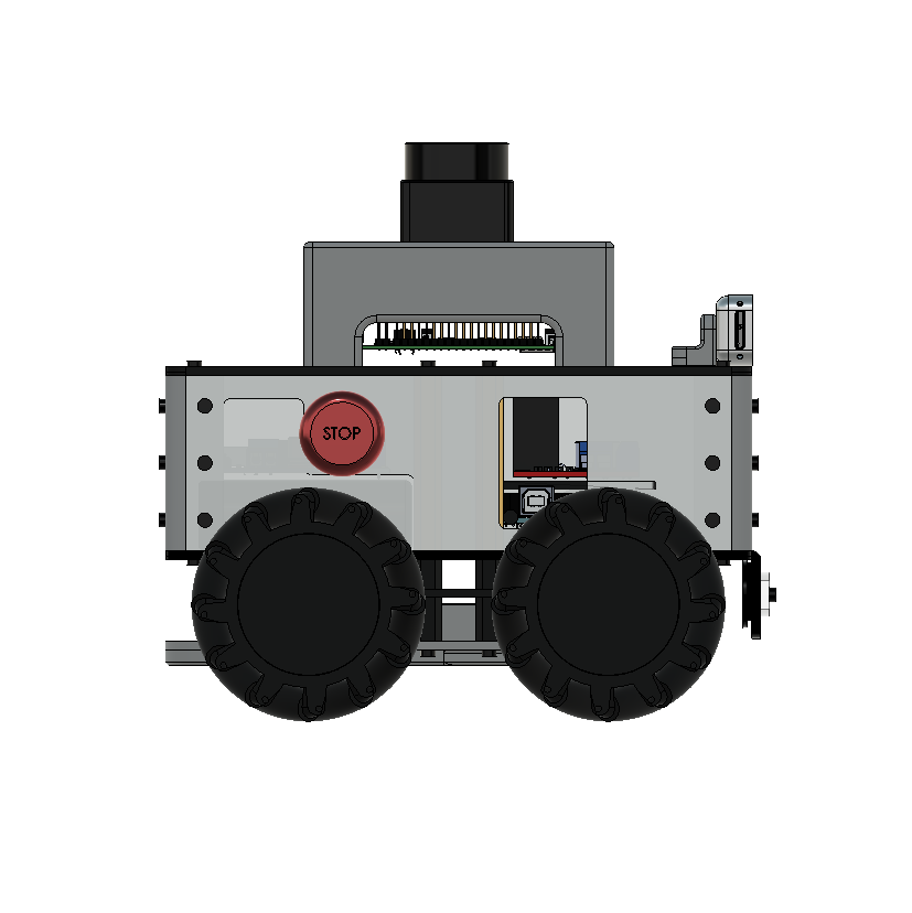
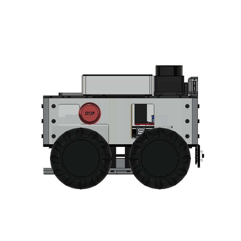
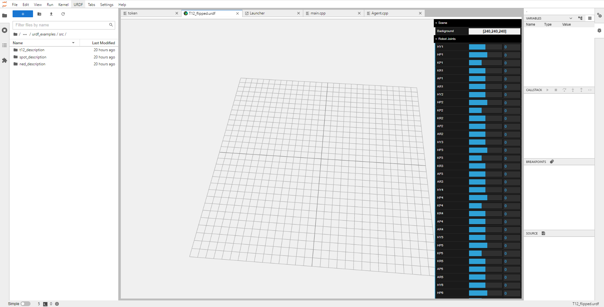
It is called jupyterlab-urdf, and is an extension for JupyterLab that allows users to create, edit and view URDFs from a browser. Their documentation shows some incredible examples of it working remotely on a browser, but it does not seem to work for me. The extension is installed and active, and I am also able to create and edit URDF files with a single button, but when I try the viewer, it shows me all the controls and settings, but a blank grid without any meshes. I haven’t been able to find a solution yet, but I only spent about an hour on it, and since this project is new, its an understandable issue and will surely be fixed soon. I might also create an GitHub issue, but first I want to repeat the steps to confirm its not a problem in my installation.
Next Steps
For the next week, maybe two, I want to focus on advanced micro-ROS topics - last week I mentioned that I was curious about the micro-ROS concepts and architecture. This week, I also realized that I skipped the rcl/rclc tutorials and missed a lot of important details. I want to try and practice these concepts hands-on instead of just reading them. Next, I want to implement another simple micro-ROS application. I have a FlySky FS-i6x RC controller and I want to connect it to the Teensy 4.1 on the AKROS robot. This way, I can takeover from the autonomous navigation nodes and drive manually or do some course corrections during autonomous operation. I will also be able to drive the robot with the RC controller, without having the RPi switched on. I first need to connect the receiver to a level shifter, so that it can talk over serial at 3.3v. This gets connected to the Teensy 4.1 expansion board and its 3.3v UART TX/TX pins. Hopefully, there should be minimal noise and data loss during the voltage shift. Once a sample application is ready, I then intend to add micro-ROS features to it, so that I can publish twist messages back to the RPi4 from the Teensy on the AKROS2 robot.
Meanwhile, I also received some of other the goodies I mentioned during the last post. One of them is the Flirc case I mentioned earlier, the second one is a Wio Terminal (an impulse purchase when I saw it on discount, I still dont have a plan for it). I had also ordered Qwiic connectors, alongside Qwiic adapters for the Wio Terminal’s Grove connectors, and also for Portenta’s Eslov self-identification port. The adapters were out of stock and I hope to receive them next week, along with my new Pico W board.
