After spending a lot of time learning and experimenting with micro-ROS/ROS2, this week I finally started porting the AKROS software from ROS Noetic to ROS2 Galactic. Since I had just finished experimenting with micro-ROS and Teensy 4.1, I decided to start porting the micro-ROS firmware first. As I mentioned before, my reference for this entire migration is Linorobot, an open source platform designed by Juan Miguel Jimeno based on ROS/ROS2 that allows multiple configurations (differential drive, skid steer and holonomic using mecanum wheels), and supports different kinds of sensors, motors and motor drivers.
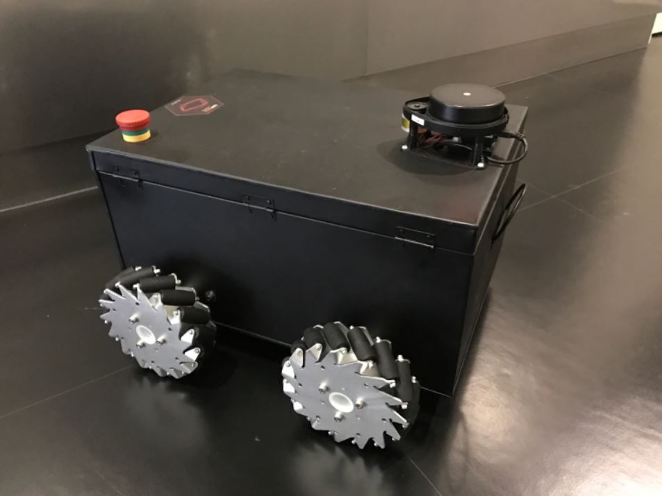
The reason I chose this as a reference because firstly, the mecanum drive configuration is nearly identical to the AKROS robot, with the exception of the IMU connected to the microcontroller instead of a T265 which I have used for the same thing. The second exception is the documentation and community, which is obviously much better with the Linorobot as it is a public project running for a few years now. I was also surprised that Linorobot’s ROS2 configuration also quite in line with my plans for AKROS2 - Nav2 (the ROS2 navigation stack) with a LD06 LiDAR (also supported by Linorobot) running on the ROS2 computer, and a Teensy 4.1 for the low level control running micro-ROS.
The Linorobot2 software stack consists of two repositories - linorobot2 and linorobot2_hardware. The first one includes the ROS2 software stack running on a Raspberry Pi or an NVidia Jetson device. The second repository contains the firmware running on micro-ROS. My first step was to fork the latest linorobot2_hardware repository (I renamed it akros2_firmware) supporting ROS2 Galactic and make it compatible with the AKROS firmware with ROSSerial (and ROS Noetic). Here are some of my notes about this process:
PlatformIO vs Arduino IDE
The first thing I noticed about the linorobot2_hardware repository, is that it uses PlatformIO, which means it uses the micro_ros_platformio library. The problem with it is that the library needs to be compiled and then uploaded to the microcontroller from a Linux machine which also has ROS2 installed. Since I’ve been using Windows 10 with the Arduino IDE and micro_ros_arduino, I thought simply replacing the headers (from micro_ros_platformio.h to micro_ros_arduino.h) will do the trick. Turns out while these two libraries are alternatives of the same thing, the functions are not identical. For example, with micro_ros_arduino, the serial transport is set with the set_microros_transports() function call, while with micro_ros_platformio, the serial port needs to be intialized first, and then the serial transport can be set, like this:
Serial.begin(115200);
set_microros_serial_transports(Serial);
So, I had to make the necessary changes to the Linorobot2 code. The second difference between the two platforms is the directory structure. The PlatformIO repository uses the following directory structure:
Root directory
	- config
		- config.h
	- lib
		- library1
			- library1.h
			- library1.cpp
			- ...
		- library2
			- library2.h
			- library2.cpp
			- ...
		- ...
	- src
		- firmware.ino
	- platformio.ini
In this structure, firmware.ino contains the main setup and loop functions, and the remaining are the used libraries and their implementations. The libraries can be included in the main sketch directly like this: #include "library1.h" or #include "config.h". However, on the Arduino IDE, things are a bit different. Arduino only allows libraries to be used in a few ways. Official releases of libraries can be installed from the library manager, or by including zipped distributions using the IDE. For users to add their own libraries, there seems to be only one way - by making a src directory (it cannot be called anything else or it won’t work) and storing all the files there. The directory structure for Arduino looks like this.
Root directory
	- src
		- library1
			- library1.h
			- library1.cpp
			- ...
		- library2
			- library2.h
			- library2.cpp
			- ...
		- ...
	- config.h
	- firmware.ino
One thing to note that these libraries cannot be included directly like in PlatformIO, but instead the full path needs to be used like this: #include "src/library1/library1.h". Once these changes were made, I was good to go. I plan on making some slight updates to the libraries themselves as and when I need them, once these changes are done, I will compress them in a zip file and include it into the project from the Arduino IDE. This way, I can include the header files directly like in PlatformIO instead of needing the full path.
Firmware updates
Once I was all set with the Arduino IDE and I was able to compile the code, I then studied the code before adding some extra features to the firmware. The code worked in the exact same way as the AKROS firmware, but in a much more object oriented way. This makes the code flexible for different configurations, with different motors/wheels and different kinematics. The main code is also structured the same way as the Reconnection example from micro_ros_arduino that I’ve tried a few times before.
The main setup only initializes the sensors and the transports, then the loop function runs a state machine that creates the micro-ROS entities when the agent is connected and destroys them when the agent disconnects. When the agent is connected, an executor is spun which subscribes to Twist messages and executes a timer, within which the control loops are executed to drive the motors and the IMU/Odometry messages are published. The firmware also includes a configuration header file which is used to define the robot’s specifications such as dimensions and speed limitations, components such as motor drivers and IMUs, and their pin configuration. I added my own changes to the firmware, these are listed below:
Ethernet transport
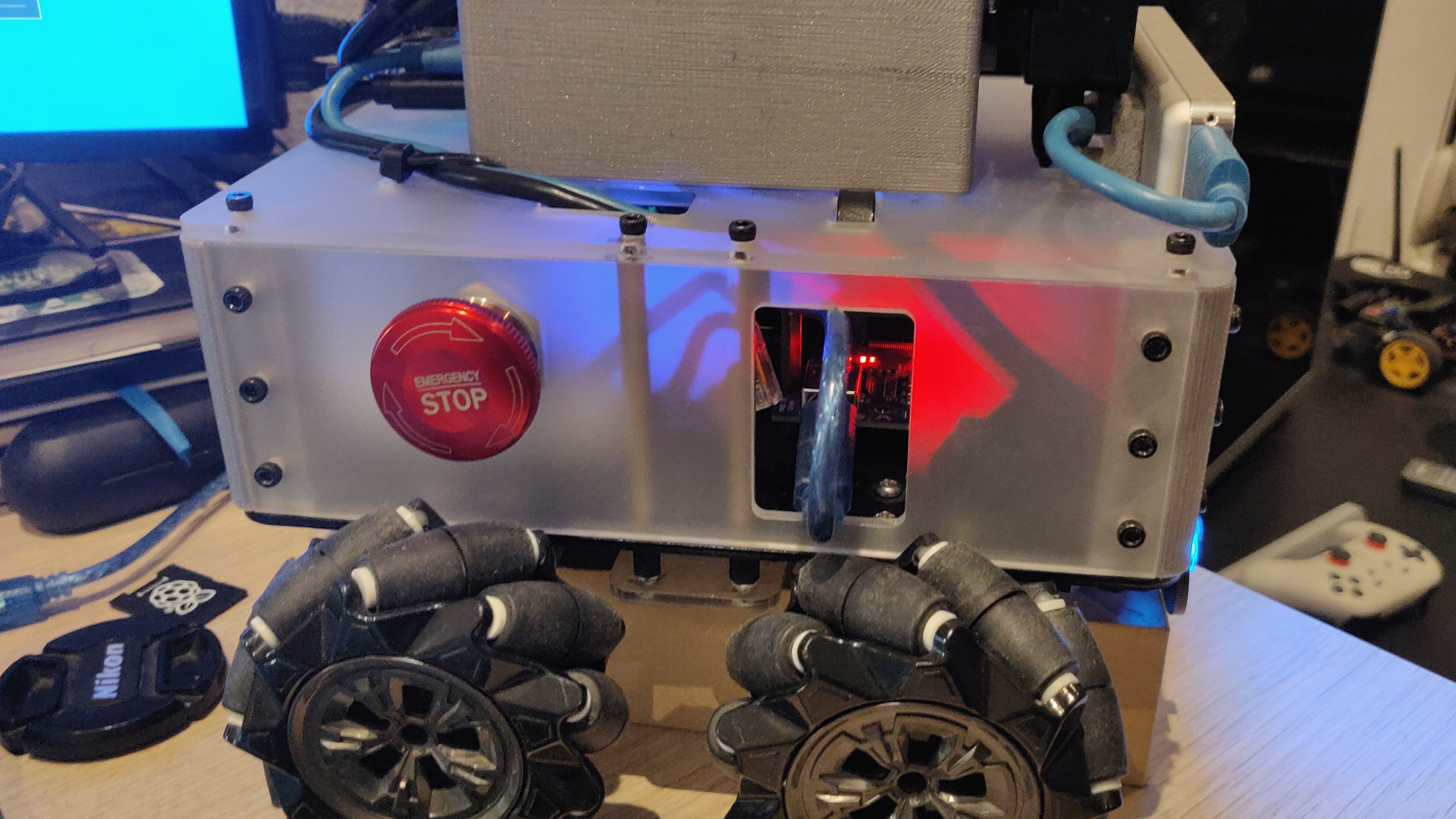
Like I mentioned in one of my previous posts, I finally got microROS to work with Ethernet on the Teensy. While I did realized a few weeks ago that serial transport can handle the required bandwidth (unlike ROSSerial) and I did not need Ethernet, I thought it would be nice to have since the expansion board has an Ethernet port. I also have a (completely accidental) opening to access the port if I need it.
For now, I added options in the configuration file (#define TRANSPORT_SERIAL and #define TRANSPORT_ETHERNET), that allow users to choose their transport type (the other one is commented out). These defines are used in the setup function like below:
    #ifdef TRANSPORT_SERIAL
        set_microros_transports();
    #elif TRANSPORT_ETHERNET
        byte mac[6];
        getTeensyMAC(mac);
        IPAddress teensy_ip(192, 168, 1, 177);
        IPAddress agent_ip(192, 168, 1, 113);
        set_microros_native_ethernet_udp_transports(mac, teensy_ip, agent_ip, 9999);
    #endif
ROS_DOMAIN_ID
I eventually will be building another ROS2/micro-ROS robot, and I want them to have separate ROS_DOMAIN_IDs, so I included this in the configuration and the firmware as well. I talked about this in a previous post.
rcl_init_options_t init_options; // global

	// in the createEntities() function
	init_options = rcl_get_zero_initialized_init_options();
	RCCHECK(rcl_init_options_init(&init_options, allocator));
	RCCHECK(rcl_init_options_set_domain_id(&init_options, (size_t)ROS_DOMAIN_ID));
	RCCHECK(rclc_support_init_with_options(&support, 0, NULL, &init_options, &allocator));
WS2812 (Neopixel) support
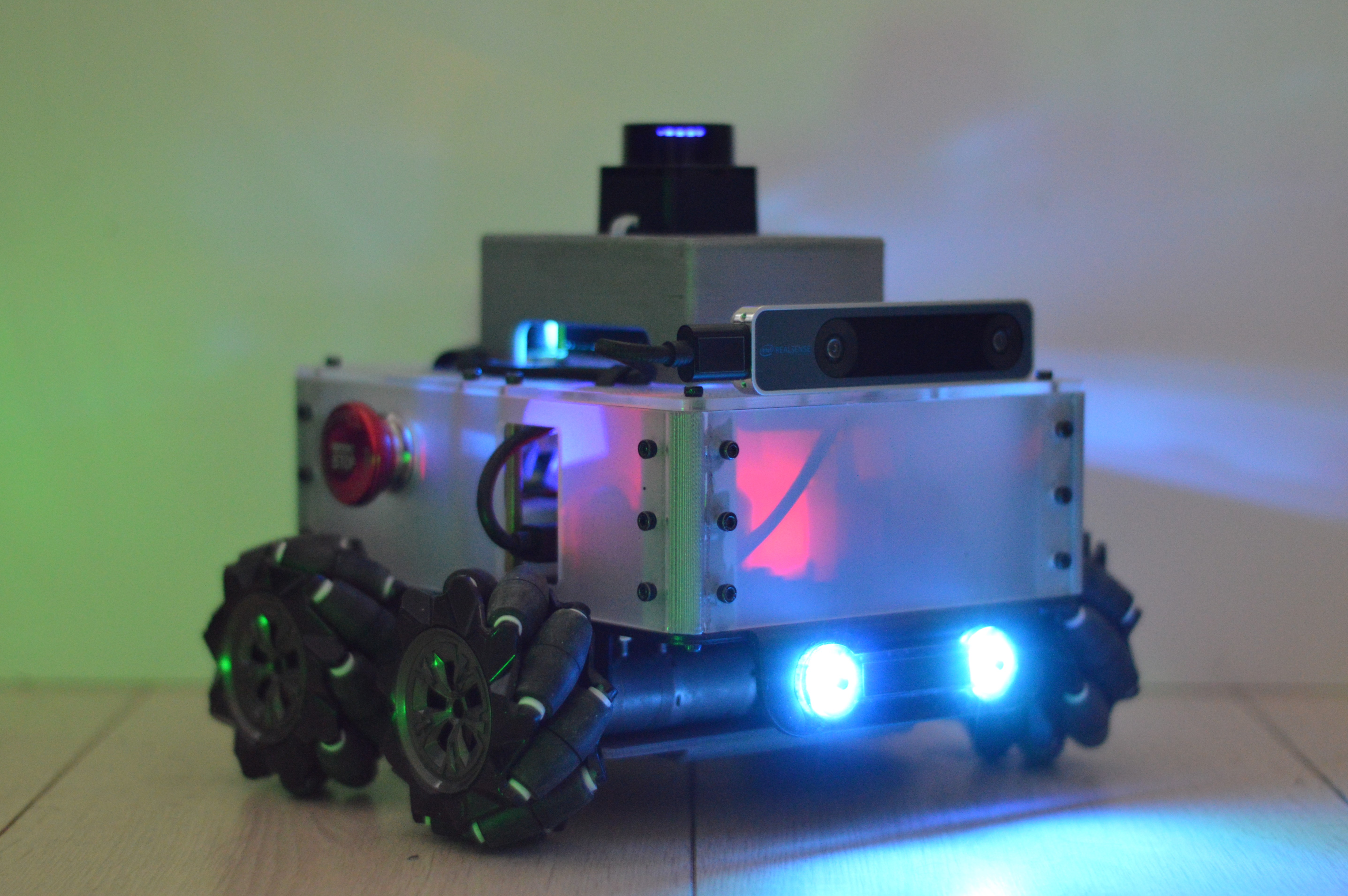
Next, I included the FastLED library (already installed using the library manager) and my functions to set the WS2812/Neopixel LED colors. These LEDs are not only fun looking eyes for the robot, but also important for indicating the robot’s status, especially to show which mode the robot is operating in (auto, teleop or e-stop), and whether it is connected to ROS or not. The latter should work with micro-ROS (unlike ROSSerial), thanks to the ability to ping the ROS2 host, as shown in the Reconnection example and here.
Mode subscriber
The Neopixels need to indicate what mode the robot is operating in. This is done by subscribing to the mode published by a node in the ROS2 system, which uses a custom message type akros_msgs/Mode. This data structure contains boolean values that describe if the emergency stop is called, and if not, which mode is the robot operating in - teleop or autonomous. During the teleop mode, the twist_mux ROS node publishes Twist messages from the PS4 controller, and during the autonomous mode, the Twist messages from the navigation stack are published. The published Twist messages are received by micro-ROS via subscription. With this Mode subscriber, the Teensy is not only aware of the mode, but can also indicate it by setting the Neopixel colors accordingly. The same colors are synchronized to the PS4 controller using another node on the ROS2 system.
In ROS Noetic with ROSSerial, I was unable to add custom message types to the libraries. Instead, I used a translation node between the ROS system and the ROSSerial node to convert the akros_msgs/Mode type to a standard integer type which can be understood by the Arduino. micro-ROS makes it a little easier to include custom message types. However, since I’ve not gotten around to this yet, I decided to add a placeholder subscription to an integer value.
With this placeholder, I can add the mode functionality - first, to set Twist values to 0 if the emergency stop enum integer is received, and second to set colors on the Neopixel based on selected mode and their corresponding colors on the PS4 controller. I can test it by publishing integer values (0 for E-stop, 1 for Teleop, 2 for Autonomous) from the command line.
Reconnection
Reconnection between the micro-ROS client and the micro-ROS agent works in two ways. First, when the client is disconnected (either by software or by physically unplugging the client) and reconnected. Second, when the agent is terminated on the ROS2 host and then restarted. In the first case, when the microcontroller device is disconnected, the agent detects this and destroys all the allocated memory on the agent side. The microcontroller is also reset, and the reconnection works. When the agent is disconnected, the microcontroller device should detect it and destroy all allocated memory. This is shown in the Reconnection example.
For me, while the first instance worked, the second instance did not. In my case, the device entered the error loop between the destruction of initialized objects and their re-creation. It took me a while to realize that there were a few things that were being initialized but not destroyed. Once I fixed it, the reconnection worked in both instances.
    // in the destroyEntities() function
	rcl_ret_t rc = rclc_executor_fini(&executor);
    rc += rcl_publisher_fini(&odom_publisher, &node);
    rc += rcl_publisher_fini(&imu_publisher, &node);
    rc += rcl_timer_fini(&timer);
    rc += rcl_subscription_fini(&twist_subscriber, &node);
    rc += rcl_subscription_fini(&mode_subscriber, &node);
    rc += rcl_node_fini(&node);
    rc += rclc_support_fini(&support);
    rc += rcl_init_options_fini(&init_options);
I was forgetting to destroy the initialization options which I had added. Additionally, in the Linorobot firmware, the subscribers were not destroyed either, so I added them as well. This also included the mode subscriber which I added (for now, still subscribing to integers). Another thing I learned is that the order of destruction matters. For example, since a node includes the entities such as subscribers and publishers, they should be destroyed before the node itself. Same goes for the support and init_options.
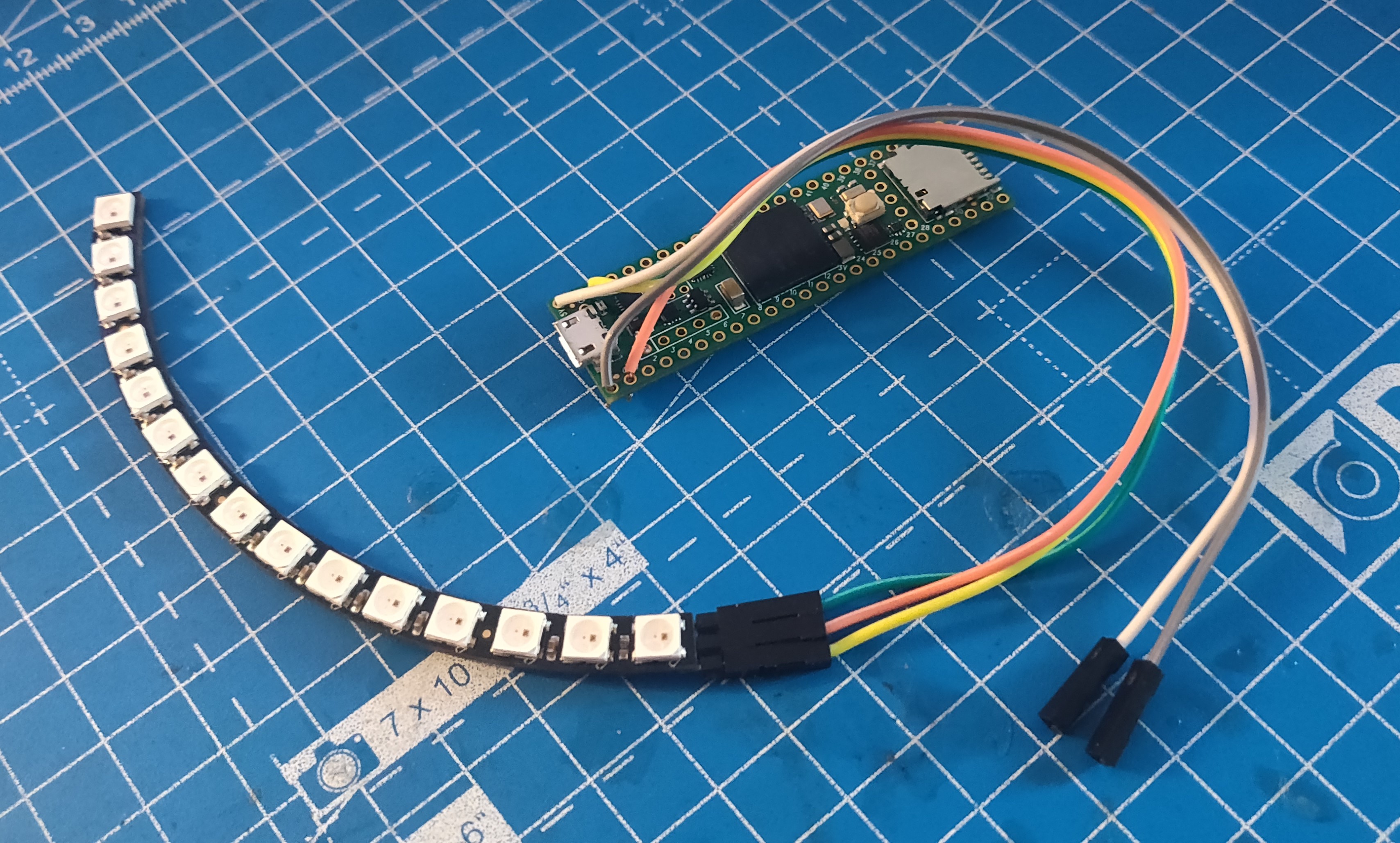
I tested all of this changes using micro-ROS running on a spare Teensy with a strip of Neopixel LEDs. I still haven’t written any ROS2 nodes yet, or built the linorobot package. I will first use ros1_bridge to use the AKROS packages to test the low level control before starting with the ROS2 nodes.
Next steps
I was going to spend some additional time practising micro-ROS this week, especially going through the advanced tutorials and setting up a working, integrated example. Fortunately, during this time I spent on updating the Linorobot2 firmware for AKROS2, I did exactly that. The work I did this week is not exhaustive, and does not contain some of the advanced tutorial concepts such as custom messages, transports and QoS. The AKROS2 firmware also does not use the parameter server for now, but I am considering using it for something. I also do not use any services either, but I don’t seem to have a use for them at the moment.
For the next few weeks, I want to focus on a few of these things, as listed below. Meanwhile, I also finished with the AKROS2 design I talked about in the last update, and placed an order for these parts. I’m expecting them to arrive in about two weeks time so I can focus on the software till then.
Calibration
The first thing I need to do is calibrate the robot, to calculate values such as max RPM and encoder CPR. While I have some of my own scripts for this, the linorobot2_hardware package has it’s own calibration sketch that produces the same values that are required for in the configuration header. The only issue I have been having with this is the directory structure of Arduino IDE I mentioned before. I seem to have to make a copy of some of the linorobot2_hardware libraries into it’s own src directory for the calibration sketch. I will continue using these copied libraries till I find a more elegant way of having multiple sketches under the same workspace, using the same libraries.
Custom messages
As I mentioned earlier, I used a subscriber to an integer message to prototype the Mode subscriber’s callback functionality. I then decided to try and build custom message types, and made the necessary changes to the firmware. I followed instructions mentioned in the micro_ros_arduino tutorial on Windows 10 and the commands worked, but nothing happened and no files were generated. I have opened an issue on the micro_ros_arduino repository, hopefully I get some feedback by the end of next week. I might have done something wrong while using Docker. I’m still quite new to the platform and so far I dont like it very much since it doesn’t seem to be documented very well.
Fused odometry
When I first saw that Linorobot uses an IMU connected to the microcontroller also doing the motor control, I thought it was being used in the odometry calculation. Turns out, I was wrong. Linorobot simply publishes IMU measurements to a separate topic and does not use it internally for computing odometry. I have always found IMU’s crucial in computing odometry for wheeled robots. Firstly, they can be used to correct for accumulated errors in the odometry calculation due to things like wheel slip. But most importantly, it solves one of the drawbacks of using wheel encoders - Wheel encoders do not work when the robot is stuck but the motors are still spinning. Wheel encoders will still continue to count it as movement. The cheapest of IMUs can very accurately detect if the robot is in motion or not, and can solve this issue with ease.
I would certainly like to implement this, if something does not already exist. I would ideally like to have three publishers, one for raw odometry, one for raw IMU data and one publishing the fused odometry data. But I do not know how well the Teensy will be able to handle these three publishers along with two subscribers and a timer. If the Teensy does not handle it, I am okay with having only two publishers - one for the raw IMU data, and one for the fused ddometry data since I will not be using the raw odometry data anywhere else.
Parameters
Unlike ROSSerial, micro-ROS provides access to the ROS2 parameter server, as explained in this tutorial. Using these parameters, a few configurations can be made to the microcontroller system during runtime. For example, using ROS2 visualization tools, users should be able to plot the published Twist messages along with subscribed Odometry messages, and then change the PID parameters accordingly. The Mode subscriber could also be replaced by parameters and the Neopixel LEDs can react when these parameters change. Similarly, all the defines within the configuration header could also be replaced by parameters if Teensy and micro-ROS can handle it, which means the robot can now be configured entirely using a ROS2 workspace rather than having to configure the microcontroller firmware separately.
There is however a drawback - memory constraints. The parameter server uses five services and an optional publisher, and also has a cap on how many parameters can be used. The Teensy might be able to handle it to some extent but many of the other microcontrollers compatible with micro_ros_arduino would not work. If I use it, I also need to be judicious about the number of parameters I include in the firmware, especially with 4 other publishers and subscribers. At the moment, I still do not know how I will use this in AKROS2, but I certainly want to give it a try.
Updated plans for the next build
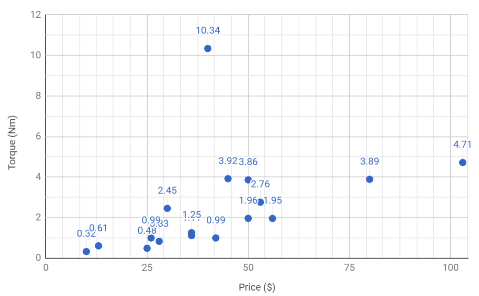
Finally, I have also diverged from my plans for some new builds this year. I started off by planning on building a legged robot, and also purchased some serial bus servo motors to prototype one leg. But I’ve scrapped these plans for now (these servo motors are not going to waste, I can certainly use them elsewhere). I’ve decided to work with BLDC motors for now, doing some simple experiments with a small motor at first, then building a bigger robot using a commercially available hoverboard. I only realized a little while ago how economical hoverboard motors are, they are incredibly rugged since they are meant to carry humans over different terrains, and are very economical since they are manufactured at such a huge scale. One can even purchase the motors directly from their manufacturers in countries like China, which becomes even more cost effective. These motors happen to have one of the best torque to price ratios among other alternatives that were speficically designed for industrial purposes.
This idea is mainly thanks to some amazing people I’ve been talking with on Twitter. Namely Serdar Abali, RoboFoundry, Taylor Alexander, Rosmo Robot and Tenacity Rover. I’ve learned a lot from their tweets sharing their progress and resources related to their progress. Some of them have their own youtube channels and blogs (which are much more useful than this one). Serdar is building robots using BLDC motors salvaged from hoverboards, while RoboFoundry attached his robot chassis components on top of a complete hoverboard. Meanwhile, Taylor is a roboticist who has been working on an open source, RP2040 based BLDC motor driver, which seems to have gained quite some interest from makers on Twitter. Now, the robots: Rosmo is a small open source robot using BLDC motors and SimpleFOC with an ESP32 and microROS. Tenacity Rover is a 6 wheeled rover platform with a rocker-bogie mechanism for suspension and a swerve mechanism on the corner wheels for steering. It might not have anything to do with hoverboards, but it’s creator has a lot of experience, knowledge and tons of amazing resources in the field of robotics. I would certainly want to build a rover like Tenacity some day, maybe I can use my (now unused) servo motors for this..
Meanwhile, the other idea of a miniature version of AKROS2 still continues, but very slowly. I have been struggling trying to figure out KiCAD on my own, and not at all enjoying the process with alternatives such as EasyEDA. I’ve asked my manager at work if I can use my company’s Altium license for personal projects, and I also plan on following some tutorials online if the request is approved. If not, I will start with some KiCAD tutorials, but when I next get some time. Meanwhile for now, I’m considering hiring someone off Fiverr who can lay out the schematic I’ve designed onto a PCB, it should be quite trivial for someone with PCB designing experience, relatively cheap for me. I’ve also still not printed out the updated chassis parts, but it is on the top of my to-do list when I next visit the office.
For next week, I plan on having some more updates about AKROS2 with micro-ROS.