This week was all about tuning the PID controllers in the AKROS2 firmware and testing it with a PS4 controller. In Part 2 (the last update), I talked about the slow performance of the controllers when I plugged in the PID gain values from the AKROS firmware. So, I need to tune them again. Normally, to tune the PID controllers, I follow a simplified version of the Ziegler-Nichols method like I talked about in this post. This requires multiple trials, and I need to build and run the firmware every time I change the gain values. This is quite time-consuming. So, I set out to find a way to tune the controllers on-line, i.e. set the PID gain values during runtime.
Parameter Server
Like I mentioned in my last update, my preferred choice for this was the Parameter Server. This allows me to set parameter values (boolean, integer or doubles) from ROS2 running on the RPi, which the parameter server (running on the Teensy with micro-ROS) can react to. In my case, the parameter values are the PID gains (doubles) and the max RPM ratio (double). The parameter server reacts to changes by updating the Kinematics and the PID controllers. Before the parameter server is implemenented, the colcon.meta file needs to be updated, so that it can handle the 5 services (and 1 optional publisher) needed by the parameter server. Once this file is updated, the micro-ROS libraries need to be re-compiled.
When the micro-ROS libraries are ready, the parameter server can be implemented as explained in this tutorial. The initialization part is added to the createEntities() function that creates and initializes all the micro-ROS entities, and which is called every time the firmware connects to the micro-ROS agent. In this function, the parameter server is initialized with options, where .notify_changed_over_dds = true is used to publish any changed parameter back to the ROS2 host, and the .max_params = 4 option limits the number of parameters to 4 - kp, ki, kd and scale (the max RPM ratio).
The parameter server is also added to the executor with the callback function paramCallback(). The four parameters are then created, added to the server, and set to their default values which are defined in the configuration file (K_P, K_I,K_D and MAX_RPM_RATIO). This way, when the micro-ROS agent is reconnected after disconnecting from the ROS2 side, the parameter server is created again with the original defaults. To make the parameter changes permanent, they must be defined in the configuration file in the micro-ROS firmware or defined in the launch file that initializes the micro-ROS agent.
Every time the executor spins, the parameter server checks if anything has changed. If there has been a change in any of the parameters, paramCallback() is called, where the value of each parameter is read, stored and updated. I had to add the setMaxRPM(float rpm_ratio) function to the Kinematics library in order to set the max RPM ratio at runtime.
void paramCallback(Parameter * param)
{
// Get parameter values from parameter server
RCSOFTCHECK(rclc_parameter_get_double(¶m_server, kp_name, &kp));
RCSOFTCHECK(rclc_parameter_get_double(¶m_server, ki_name, &ki));
RCSOFTCHECK(rclc_parameter_get_double(¶m_server, kd_name, &kd));
RCSOFTCHECK(rclc_parameter_get_double(¶m_server, rpm_ratio_name, &rpm_ratio));
kinematics.setMaxRPM(rpm_ratio);
motor1_pid.updateConstants(kp, ki, kd);
motor2_pid.updateConstants(kp, ki, kd);
motor3_pid.updateConstants(kp, ki, kd);
motor4_pid.updateConstants(kp, ki, kd);
}
Finally, the created entities and the parameter server infrastructure need to be destroyed when the agent is disconnected. This is done by simply adding one line to the destroyEntities() function. This destroys all created micro-ROS entities, including the intialization options.
rc += rclc_parameter_server_fini(¶m_server, &node);
With this, the parameter server is implemented. However, this alone cannot be used to tune the PID controllers using ROS2. I also need a way to analyze/plot the measured and reference RPMs (feedback) of each motor. This data is avaialable in the micro-ROS firmware and needs to be published to the ROS2 host.
Feedback Publisher
For this publisher, I used two custom message types - akros2_msgs/Velocities and akros2_msgs/Feedback, where Feedback is a complex message which includes a timestamp and two elements of the Velocities type. These messages can be seen below:
# akros2_msgs/Velocities
float32 motor1
float32 motor2
float32 motor3
float32 motor4
# akros2_msgs/Feedback
std_msgs/Header header
Velocities measured
Velocities required
To use these new message types in micro-ROS, I first had to re-compile the micro-ROS libraries as explained in Part 2 of this series. Also, in order to get them working in ROS2, I had to copy and build them in my ROS2 workspace as well.
The feedback publisher publishes the Feedback message type, which includes a header (with the timestamp), and the current and required velocities for each motor. I intended to use the std_msgs/Float32MultiArray at first, but I wasn’t able to get it working. There seeems to be a solution for my issues, but there seems to be a lot of overhead in the message content itself, as well as in the code to use this message type, so I will stick with my solution for now.
Adding the publisher was simple - first add it to the intialization and destruction functions just like the publishers I already have. In the main body of the code, I have a function publishData to populate the message types and publish the data every time the timer is called. I added this new publisher there in the same way. After verifying that the code compiles, it was time to do some testing.
Testing
First, I tested to see if the parameter server was working. To do this, I used the command line tools to list the parameters, get their values, and to also set the values. I used the following commands and got the following responses:
$ ros2 param list
/akros2/base_node:
  kd
  ki
  kp
  scale
$ ros2 param get /akros2/base_node kp
Double value is: 0.75
$ ros2 param set /akros2/base_node kp 1.0
Set parameter successful
It is important to note that in the last command, since the gain values are defined as doubles, it is important for the value to be specified in this format as well. So, it has to be defined as ‘1.0’ instead of ‘1’, otherwise it will throw an error.
Next, it was time to begin the entire system test. First, I opened a few terminals and sourced the ROS2/micro-ROS underlays and overlays. In the first terminal, I connected to the micro-ROS agent (the Neopixels turned from Cyan to Green). A second terminal was used to run teleop_twist_keyboard and the final terminal was used to set the parameter values. I first set the linear velocity to make the robot move it’s motors forward. Then, I was able to confirm that the PID controllers were being updated by setting the parameters and observing visible differences in the motor speeds. With this, I was ready to tune the PID controllers.
PID Tuning
To tune the controllers, I also need to plot the measured vs reference RPMs. I intended to use Foxglove Studio, so first on new terminal, I launched the ROSBridge server, and connected to it using Foxglove. On Foxglove Studio, I was able to use the Plot panel to plot required and measured RPMs of the motor.
Earlier, I had realized the difference between the PID implementations of AKROS and AKROS2. In my first implementation, the PID controller returned values in the range of [-255, 255]. In AKROS2, using the Linorobot2 configuration on the Teensy, the full 15 bit PWM is used, which means the max PWM is 2^15-1 = 32767, and the PID output range is [-32767, 32767]. So, the max PWM and the corresponding output range of the PID controllers have been scaled up by a factor of 128. So, for my first try, I multipled my original PID gains by 128. The original PID gains were kp = 0.75, ki = 0.50, kd = 0.50, and the scaling resulted in kp = 96.0, ki = 64.0, kd = 64.0. Not surprisingly, it worked quite well.
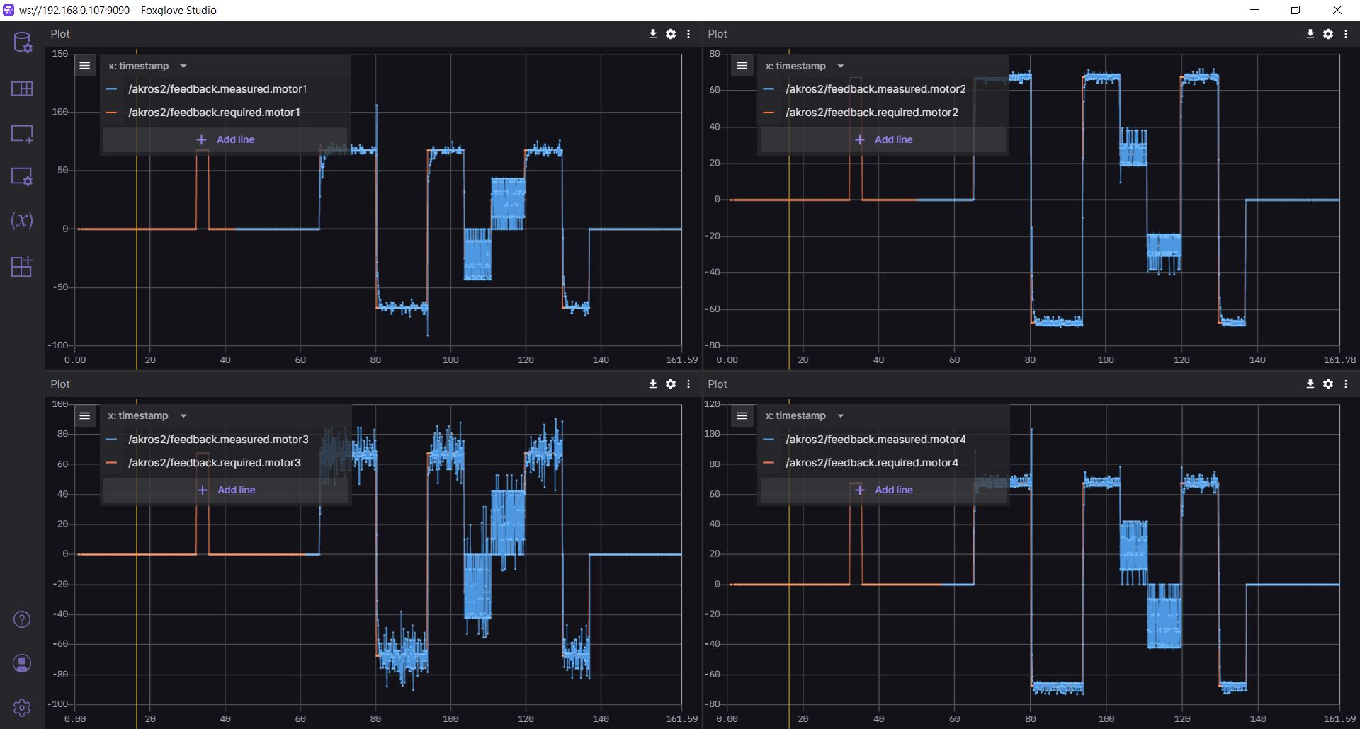
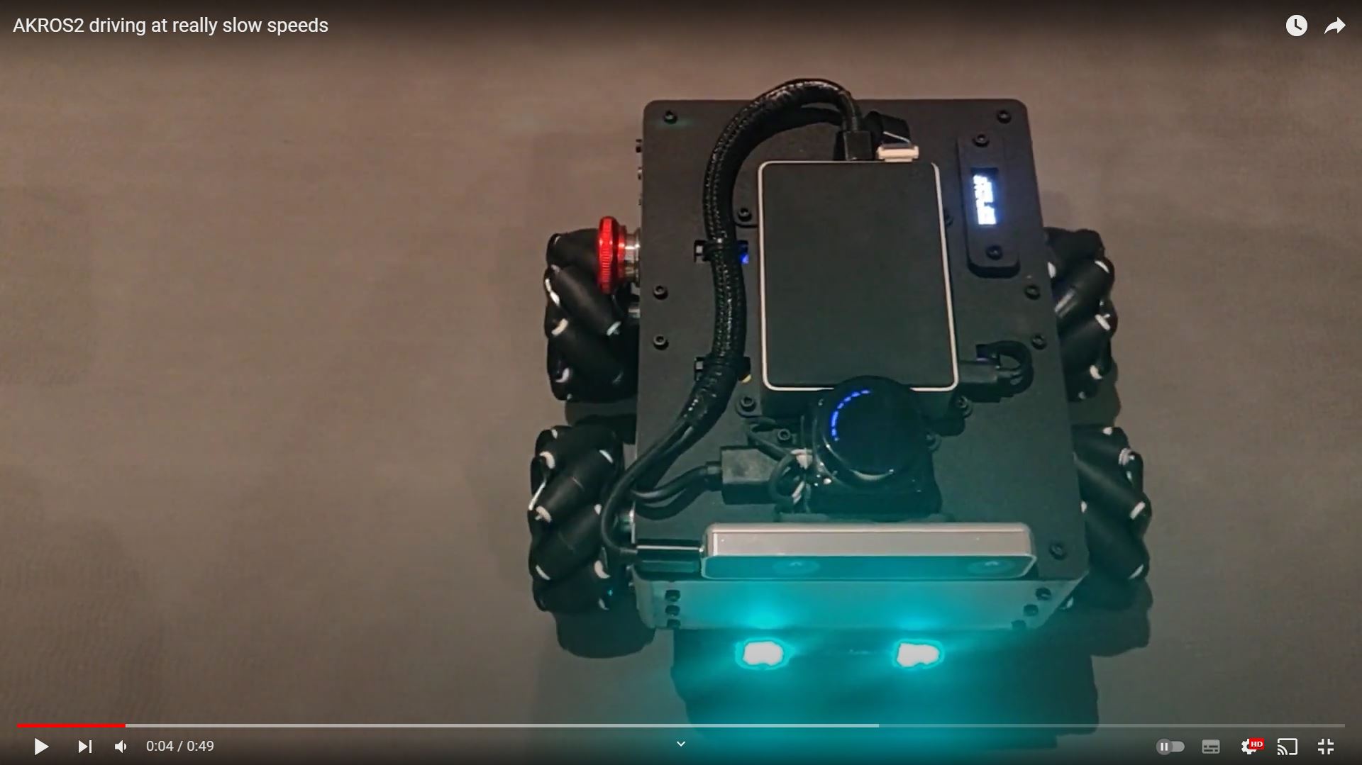
However, there were still a few issues - First, I observed that there was a lot of jitter in the motors, and this was really visible at low speeds. Next, when commanded to drive in a straight line, the robot eventually drifted to the right. I tried different values for the PID gains, and I event tried re-tuning it from zero using the Ziegler-Nichols method, but the issues still remained. I eventually realized that when driving the robot in a straight line, the RPMx were constrained to a particular MAX_RPM_VALUE, so the motors couldn’t spin faster to compensate for drifts. Increasing MAX_RPM_RATIO from 0.50 to 0.70 fixed the drift significantly. I also scaled the PWM resolution back from 15 bits to 8 bits (i.e. PWM_MAX = 255), which meant I could use my original PID gain values from AKROS instead of the new scaled-up ones. This time, after a bit of tuning, the PID values were chosen to be kp = 0.80, ki = 0.60, kd = 0.40.
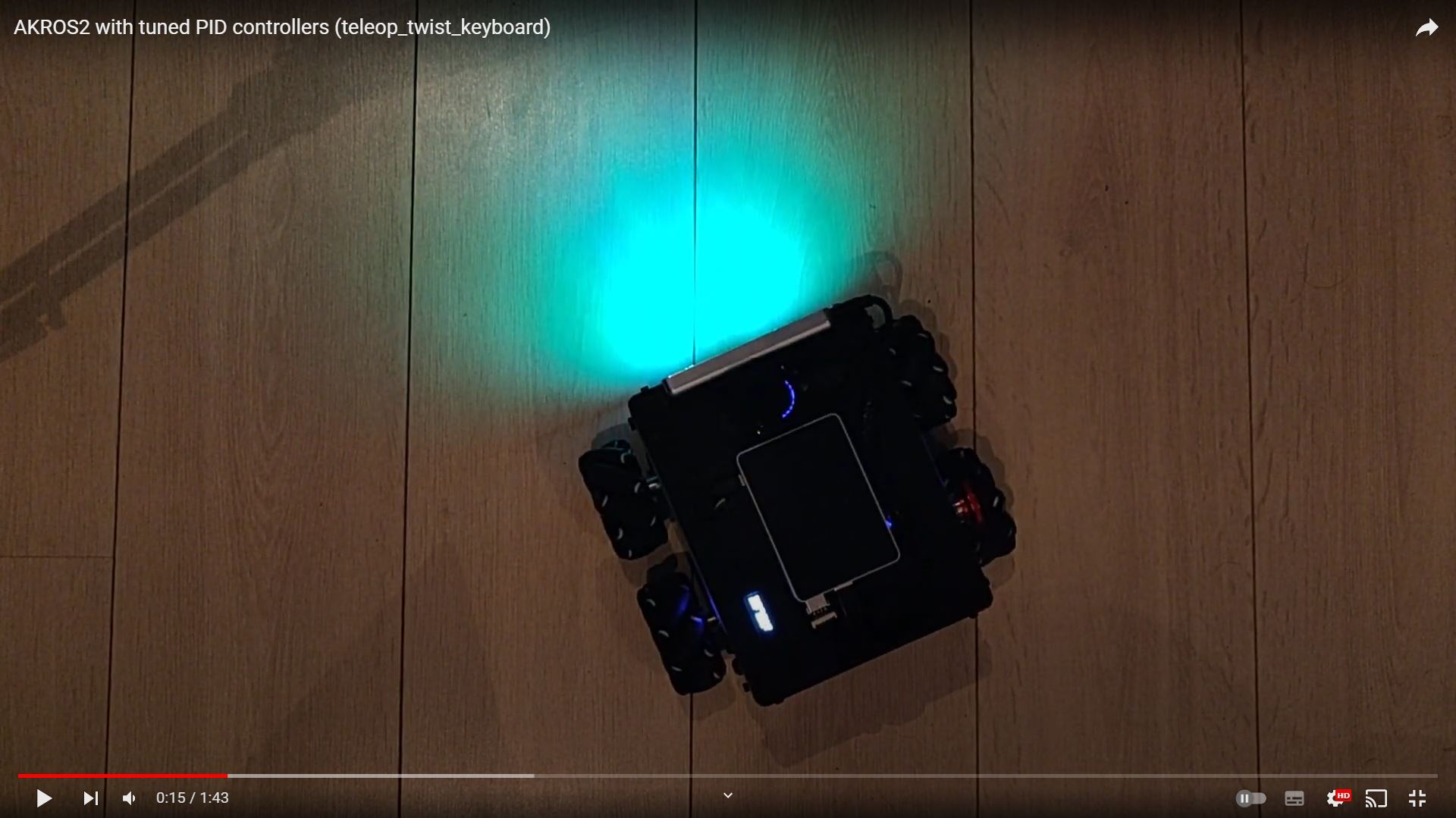
These changes seem to have fixed both issues, the jitter in the motors is significantly lower, and the drift has more or less gone. With this change, the structure and functionality of the AKROS2 firmware is now identical to the AKROS firmware, since it uses the same libraries (PID and Encoder) and now all the same constants (PWM resolution, PID gains, max RPM ratio, hardware dimensions). The only difference between two is just the kinematics implementation - in AKROS, I implemented the functionality in the main code itself, but in AKROS2, I use the Kinematics library from Linorobot2. The results with the AKROS2 firmware can be seen in the video below (using teleop_twist_keyboard):
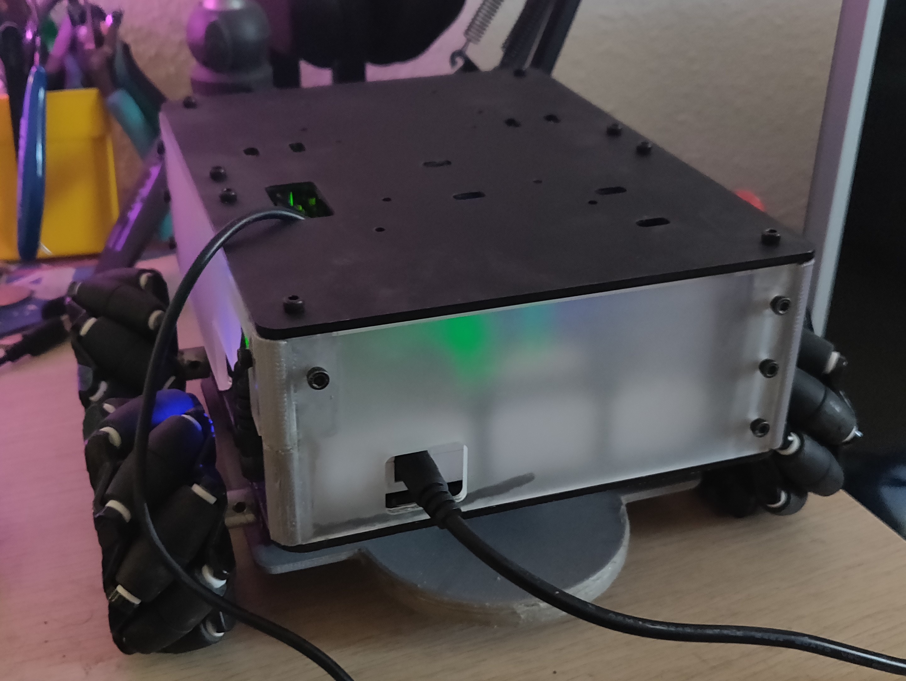
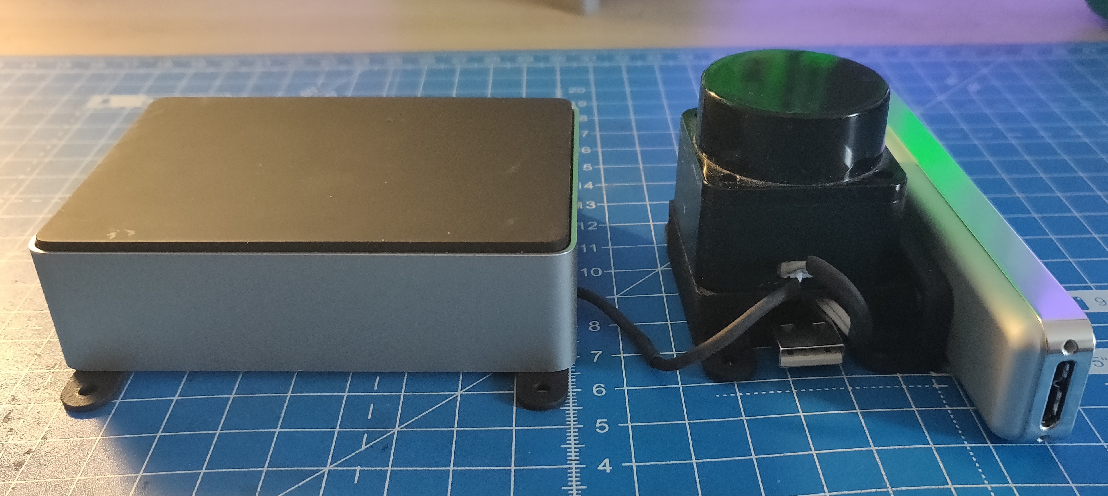
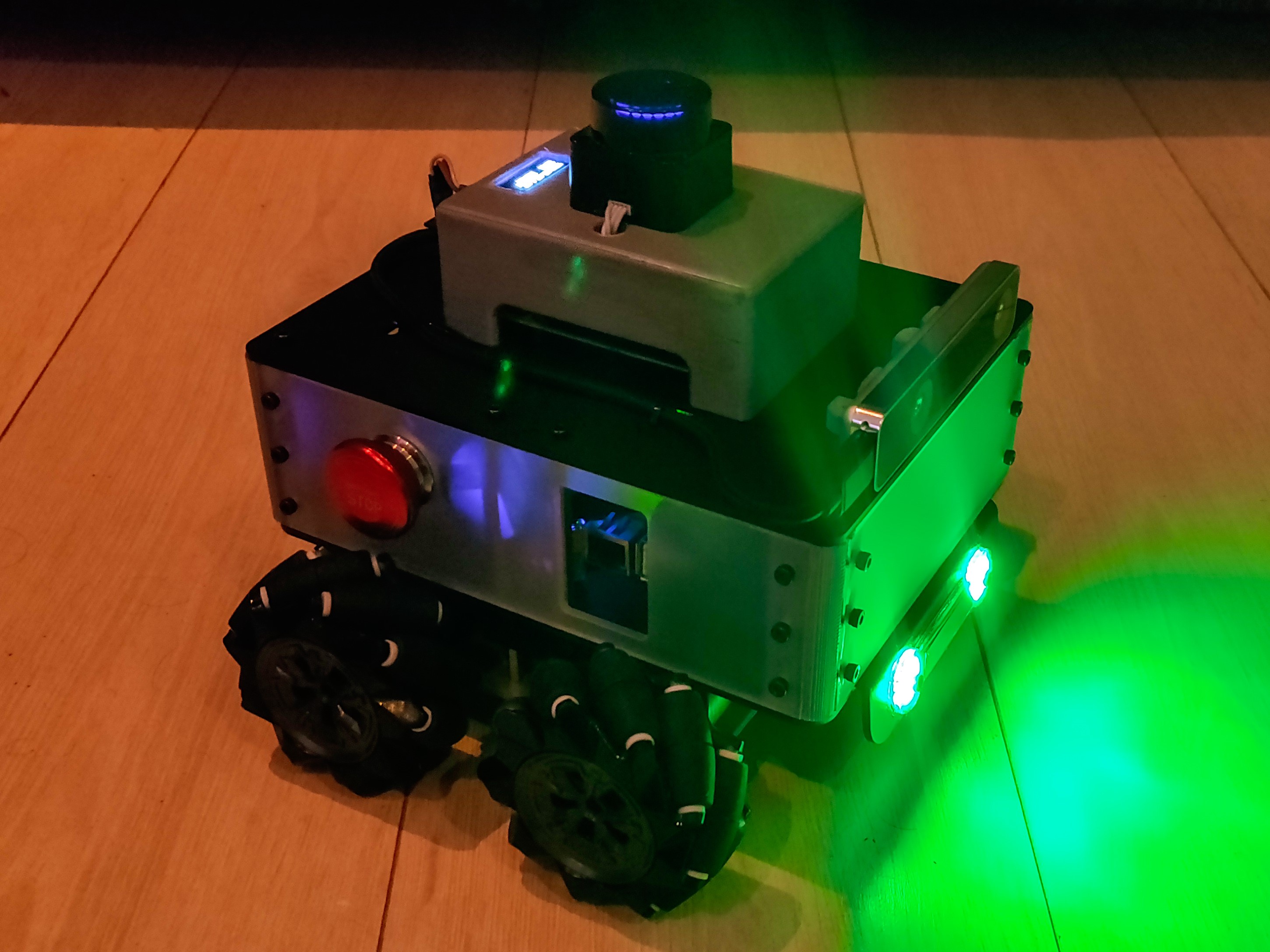
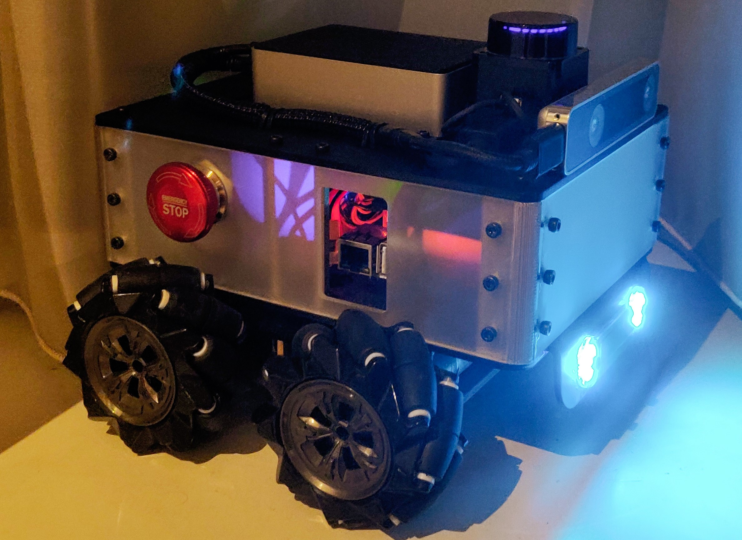
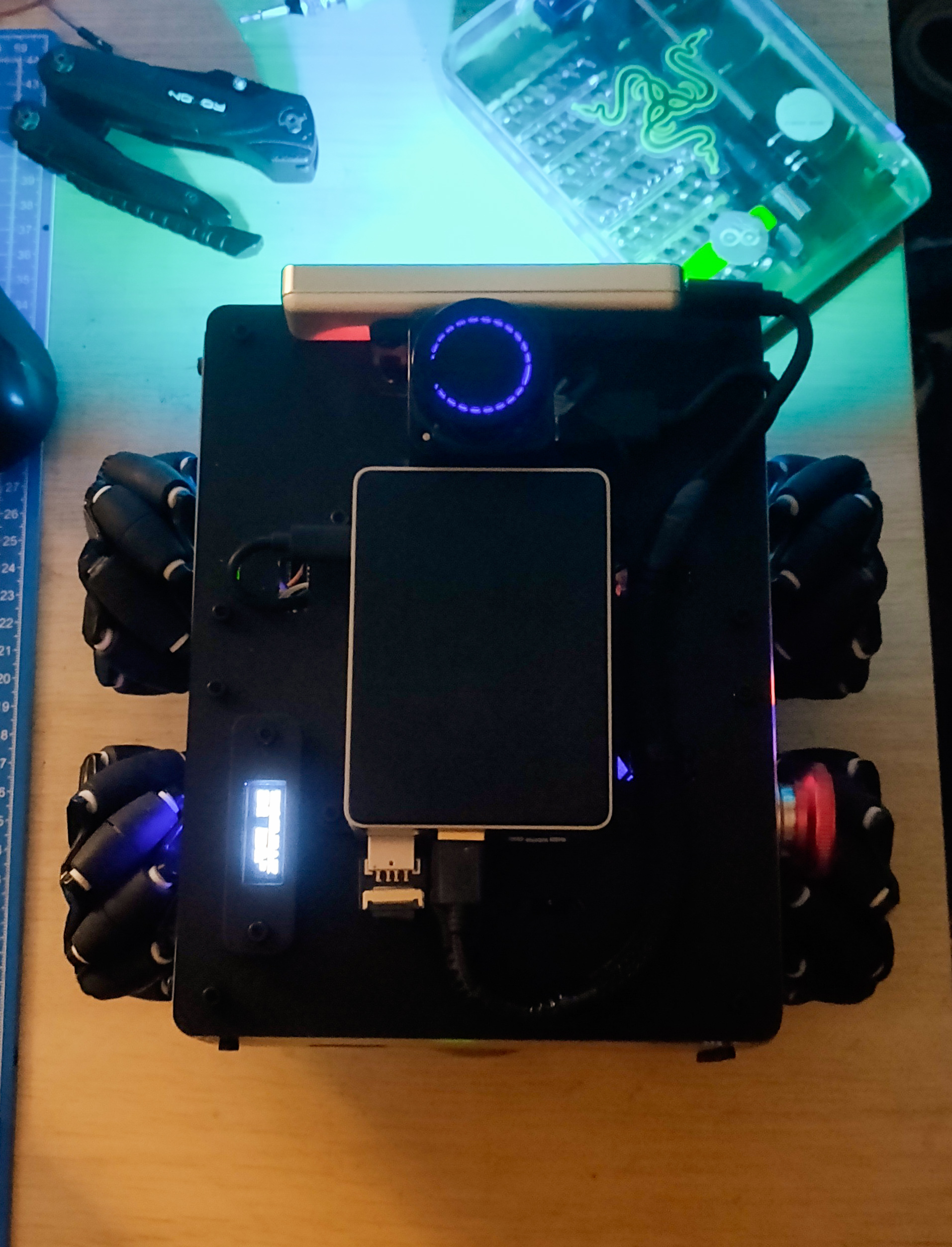
New Parts
As seen in the above video, the new parts are here! I finally was able to collect some 3D printed parts, and received the new laser-cut base plate. Like I mentioned in an earlier post, these new parts allow me to move the Lidar to the front of the robot and replace the 3D printed RPi housing with a much more compact Flirc RPi4 Case. The new case passively cools down the Raspberry Pi thanks to the aluminium housing that acts as a heat sink. I also added a separate attachment to hold the OLED display, to display stats such as the IP address and the memory usage. This entire assembly makes the robot much more compact, which also allows me to add another level above in the future. This means I could add a camera or a robot arm for example.
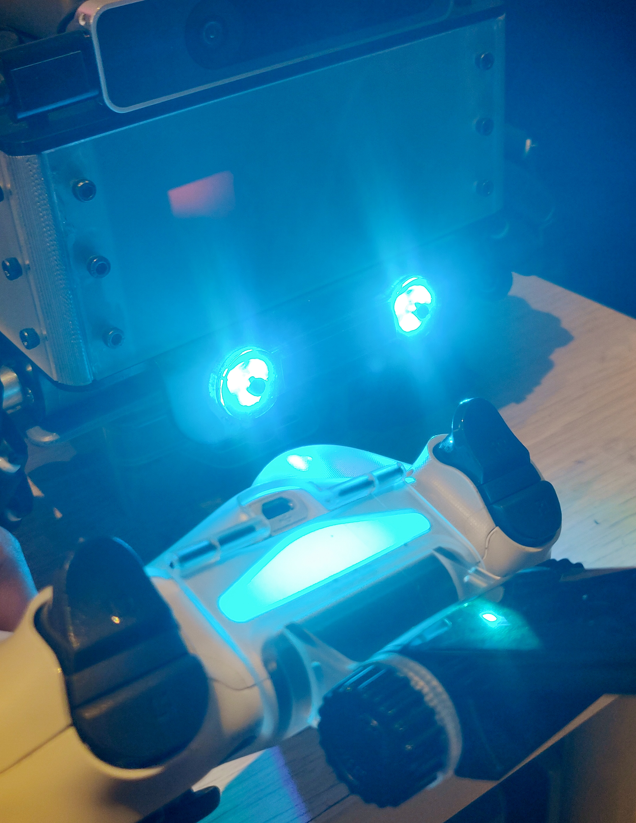
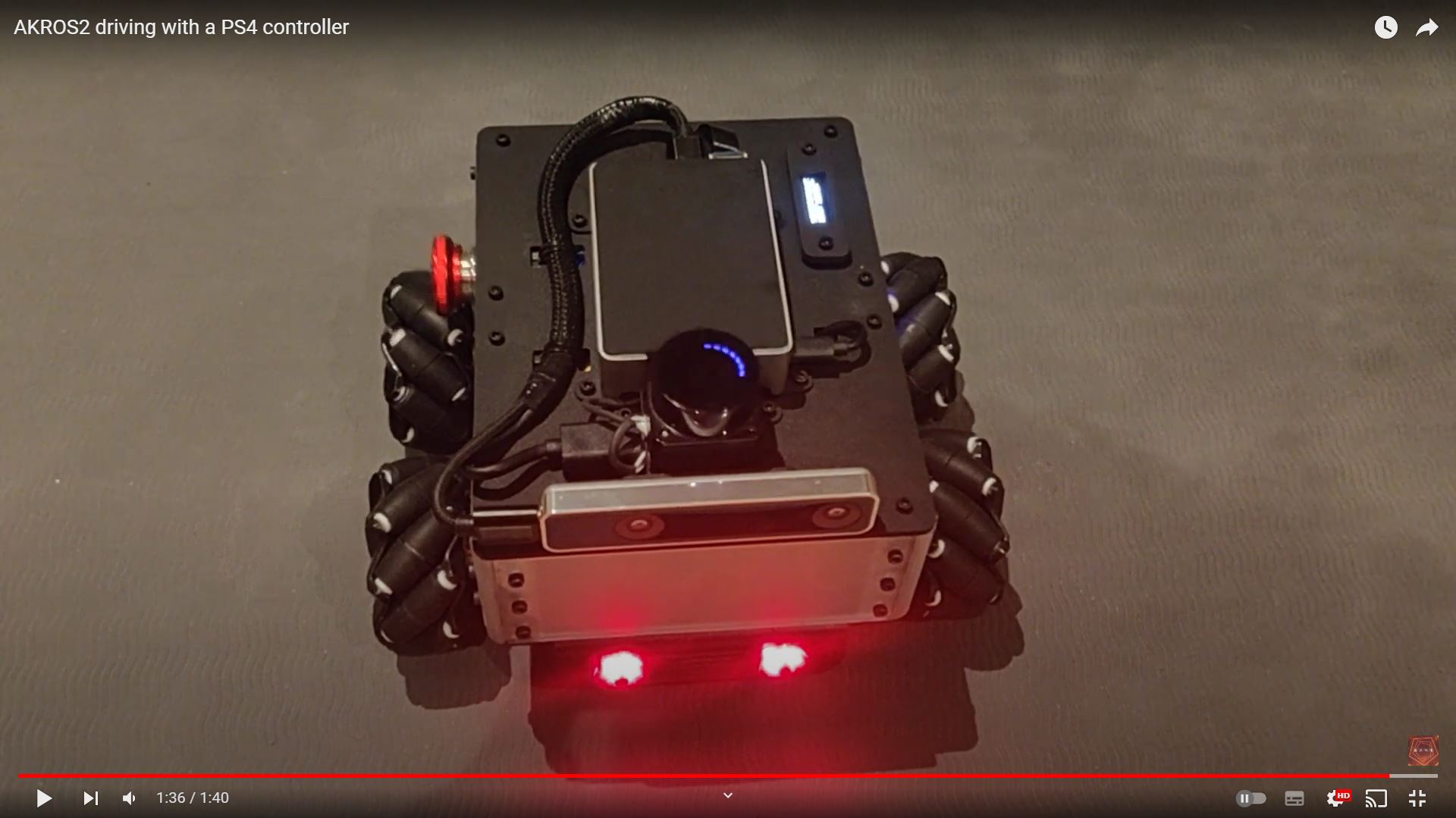
PS4 Control
Next, I worked on controlling the robot using a PS4 controller. For this, I used the ds4_driver package, which has branches for both ROS1 and ROS2. This package connects to a PS4 controller over Bluetooth and provides nodes to publish twist messages using joystick inputs, and to set the feedback message, which is used to change PS4 controller’s LED colors and to set/unset the rumble. In ROS1, I implemented this driver, where I re-used the twist publisher and wrote my own feedback publisher to (1) publish mode messages based on button presses, (2) set LED colors based on the mode, and (3) set/unset the rumble value based on button presses.
So, migrating it to ROS2 was quite straightforward - clone the ROS2 branch of the ds4_driver package, and migrate my python script (that sets the modes and feedback) to ROS2. First, I decided to implement only the ds4_driver package using the foxy-devel branch, just to make sure that the twist publisher worked. But it did not work with ROS2 Galactic straightaway. In Galactic, the parameter server has been updated in comparison with Foxy, where in the parameters cannot be declared without a default value or a default type. Also, as explained earlier in the micro-ROS parameter server section, in Galactic, the parameter server does not integer values when the parameter is defined as a double. Very strange, but the fix was easy. I also created a pull request with these changes, and it has already been merged.
Once the driver was ready and tested, I made a ROS2 package called akros2_teleop and migrated the ROS1 python script to this package. Of course, I had to make changes to the code, but eventually this worked as well. One thing that bugged me in the ROS1 implementation was the default color of the PS4 controller LED, which is dark blue. I wanted it to be cyan like the micro-ROS implementation, so I added a udev rule to set the LED color to cyan when connected.
I also migrated the launch file that launches the PS4 driver and the PS4 twist node from the ds4_driver package, and finally launches the feedback node from the akros2_teleop package. In ROS2, there are multiple ways of defining a launch file, and I went with the easier ROS2 Launch XML format, which uses the same structure as a ROS1 launch file, with only minor syntax changes. Unfortunately, one of the things that has not been migrated to ROS2 is conditional declaration using if and unless. In ROS1, it looked like this:
<node ...>
  <param name="x" value="0.0" if="$(arg condition)" />
  <param name="y" value="1.0" unless="$(arg condition)" />
</node>
I cannot do this in ROS2 anymore, so I simply removed conditions like these from the launch file. I’m pretty sure conditional declaration is possible using a python launch file, but I need some more time to understand how it works before implementing it. I am still unsure if it is possible or not to add conditions in the XML launch file, so I asked it on ROS Answers for now, and I’m still waiting for a reply.
Next Steps
For the update, I want to finish off the last bit of the advanced micro-ROS tutorials by learning about micro-ROS Tracing. Next, I want to start planning how to fuse the IMU and odometry in the micro-ROS firmware itself. This should then be the last micro-ROS thing I did before I moved on to the main ROS2 side. The first thing I want to do in ROS2 is set up the twist_mux that multiplexes through multiple Twist publishers, based on a user-defined priority. Next, to prepare for the Nav2 implementation, I need to update the URDF with the new navigation module, and then implement the ROS2 drivers for the LD06 Lidar and the Realsense T265 Camera.
In other news, my company also approved my request to attend ROSCon 2022 in Japan! It is a long story, but this almost did not happen due to a company policy that prohibits personal holidays clubbed with business trips. But a holiday can wait, I also get a 90 day (multi-entry, I think) visa, so I do have an opportunity later… I already booked tickets, but had quite a hard time to choose between the ros2_control and Open-RMF workshops. Eventually, I went for ros2_control, as Open-RMF seemed like something I could learn by myself.