This week, I planned on taking a few days off since I felt a bit burnt out at work. Surprisingly, it took only a few hours of binging Taskmaster for me to start feeling better. On day two, I started working on the AKROS2 robot, with a focus on updating the firmware. Essentially picking up where I left off last time. There were a few more updates along the way, I’ll elaborate in the next few sections.
Firmware updates
I had three main goals for this week, (1) recompiling micro-ROS libraries to use custom messages, (2) adding an IMU, and (2) running the calibration sequences to get the robot’s specifications. These specifications are then saved in a configuration file that is included in the main firmware. I also wanted to test the firmware on the actual robot, with its correctly calibrated specifications.
Custom messages
In the last update, I used the akros2_msgs/Mode type, which is a structure with two boolean values -
bool estop
bool auto_t
Where estop indicates if the emergency stop button has been pressed (on the PS4 controller only, it does not check the physical e-stop) and auto_t indicates whether the robot is in teleoperation mode (using Twist messages from a PS4 controller) or accepting twist messages from an autonomous navigation package like Nav2.
Currently, with ROS1, I was unable to send custom message types to the Teensy board using ROSSerial. Instead, I use a simple translation node that subscribes to these mode messages and publishes an integer which the ROSSerial node can subscribe to. Based on these integer values, the Teensy then sets colors on the Neopixel LEDs to match the colors on the PS4 controller.
With ROS2 and micro-ROS, I had the same issue last week. I was unable to recompile my fork of micro_ros_arduino with custom modes and instead added a placeholder integer subscriber like in AKROS (ROS1). Fortunately, I had more success this week. Turns out it was indeed a problem in the Docker file, because of an incompatibility between Windows and Unix. The fix was merged this week and I was able to verify it and close the issue I had opened.
Before adding custom messages to micro-ROS, a few changes need to be made to the package as explained in this tutorial. In CMakeLists.txt, the following lines need to be added before the ament_package() line:
find_package(rosidl_default_generators REQUIRED)
rosidl_generate_interfaces(${PROJECT_NAME} "msg/MyCustomMessage.msg")
The following lines need to be added in package.xml:
<build_depend>rosidl_default_generators</build_depend>
<exec_depend>rosidl_default_runtime</exec_depend>
<member_of_group>rosidl_interface_packages</member_of_group>
Once the message package is ready, there are two ways to add them to the micro-ROS libraries. The first way is to copy the akros2_msgs package to extras/library_generation/extra_packages inside the micro_ros_arduino repository. The second one is to create a GitHub repository and add it to extras/library_generation/extra_packages/extra_packages.repos like this:
repositories:
  akros2_msgs:
    type: git
    url: https://github.com/adityakamath/akros2_msgs
	version: master
I used the second option, using the akros2_msgs Github repo. Next, the extras/library_generation/library_generation.sh file must be updated, so that micro-ROS is recompiled for only the necessary target devices. Otherwise, it takes hours to finish. This can be done by commenting out the devices that are not needed. For me, I only need one platform:
if [ $OPTIND -eq 1 ]; then
    # PLATFORMS+=("opencr1")
    PLATFORMS+=("teensy4")
    # PLATFORMS+=("teensy32")
    # PLATFORMS+=("teensy35")
    # PLATFORMS+=("teensy36")
    # PLATFORMS+=("cortex_m0")
    # PLATFORMS+=("cortex_m3")
    # PLATFORMS+=("cortex_m4")
    # PLATFORMS+=("portenta-m4")
    # PLATFORMS+=("portenta-m7")
    # PLATFORMS+=("kakutef7-m7")
    # PLATFORMS+=("esp32")
fi
Once done, from within the micro_ros_arduino directory, I ran the following commands (from Windows Powershell). With the fix, the following commands should work as expected on Windows 10.
docker pull microros/micro_ros_static_library_builder:galactic
docker run -it --rm -v ${pwd}:/project --env MICROROS_LIBRARY_FOLDER=extras microros/micro_ros_static_library_builder:galactic
With the compilation finished, I could include #include <akros2_msgs/msg/Mode.h> directly and use it just like standard message types. Since I need to publish this message type from the ROS2 computer, I also made a copy of the akros2_msgs package in the micro-ROS workspace (same workspace with the micro-ROS agent) on the AKROS robot. I tested the communication to make sure I can read mode messages from the Teensy, and publish them from the Raspberry Pi. It works! Next: time to add an IMU before calibrating the robot.
IMU
My goal was only to add an IMU and make it work with the firmware. I left the calibration for later. First, I had to dig into my electronics box to find any spare IMUs, especially the ones that are already compatible with Linorobot. I ended up finding an MPU9250 and an MPU6050. I first tested them to see if they worked, which they did. Next, it was time to choose which one to use. I did not care for how accurate they are since I am only going to use it to detect if the robot is in motion, and I would rather use the Realsense T265 IMU for sensor fusion. So, either IMU would do.
The next concern was how to mount the IMUs. I did not want to mount the IMUs to the Navigation module since I dont want wires running all the way to the Teensy in the Base module. So, I had to find place in the Base module itself. I finally decided on mounting it on top of the motor drivers using brass spacers. This made the choice easy - the MPU6050 fit very well, but its headers (pointing upwards) prevented the Navigation module from fitting. On the other hand the MPU9250 has headers pointing downwards, which after bending do not touch the motor drivers (there is a gap of at least 5mm). I also added some insulation to make sure there is no contact between the IMU and motor drivers.
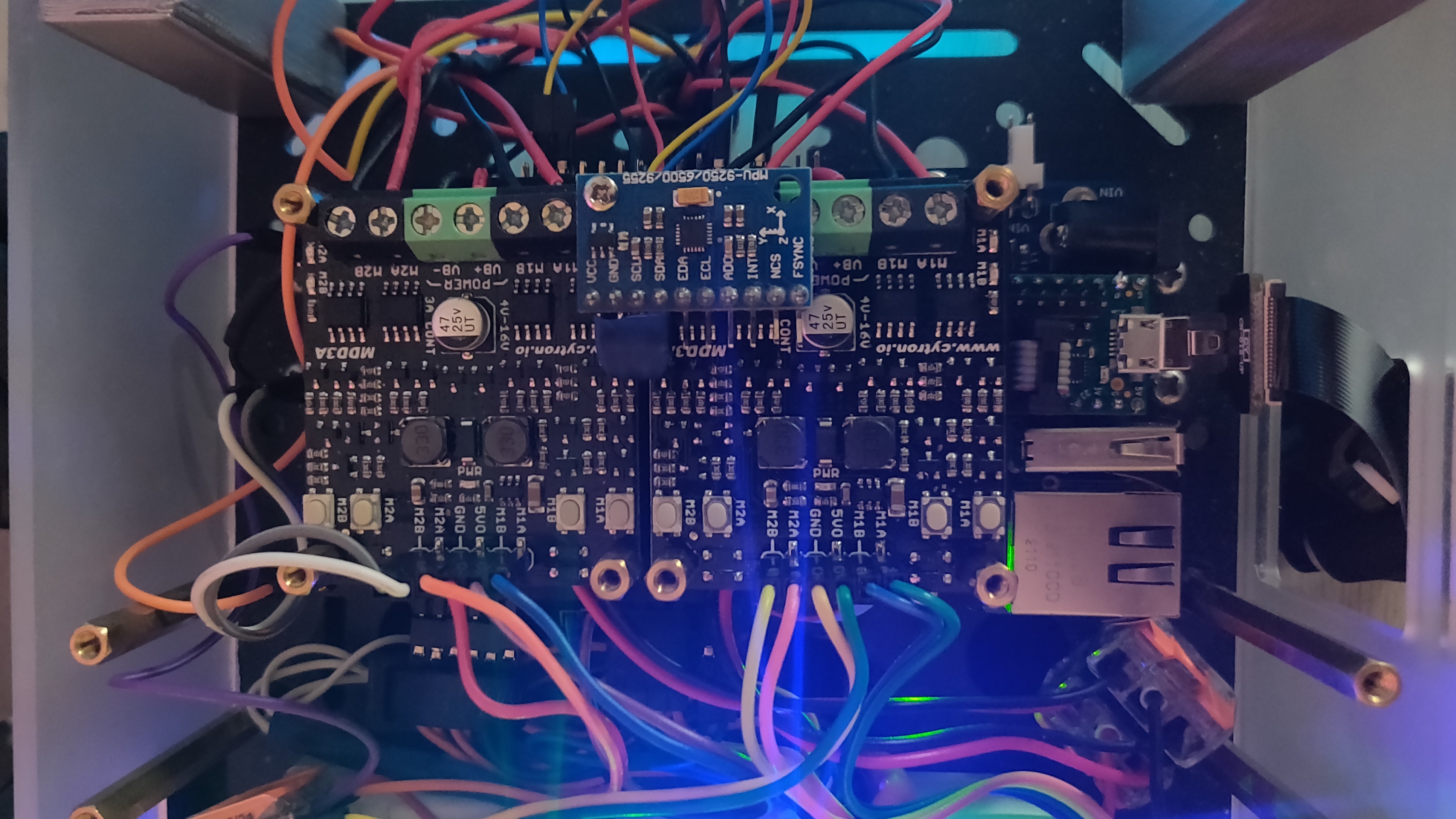
With MPU9250 attached securely to I2C0 on the Teensy 4.1 board, I first wrote a simple sketch to read the IMU data and publish it to the serial monitor. Once I was able to read data from the IMU, the next step was to run the Linorobot calibration sketch.
Calibration
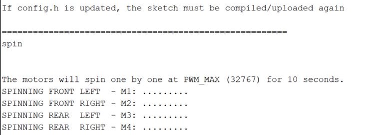
I decided to dig deeper into the calibration sketch from linorobot2_hardware. The calibration sketch has two sequences that cycle through the available motors as defined in the configuration, and spins each motor for 10 seconds. Before the loop, it sets the encoders to zero and the encoder readings are updated as the motor spins, using interrupts. The same sequence is run both times, the only exception being that one of them generates a report with extra calculations such as total encoder counts, counts per revolution (CPR) and maximum velocities. It uses the serial monitor on the Arduino IDE to select these sequences and display the reports. Unfortunately, the calibration sketch does not currently calibrate the IMU but I intend to add that in the future.
The Linorobot2 calibration sequence assumes that the maximum RPM of the motor is known, and calculates the CPR based on it. From my experience, the max RPM of hobby DC motors are never exactly what the manufacturer says. In my case, the motors were part of a kit and this info was not even mentioned in any documentation. In previous projects, including AKROS, I have had more success in relying on the CPR of the motor encoders to then calculate the maximum RPM. So I decided to change the calibration sequence a little bit.
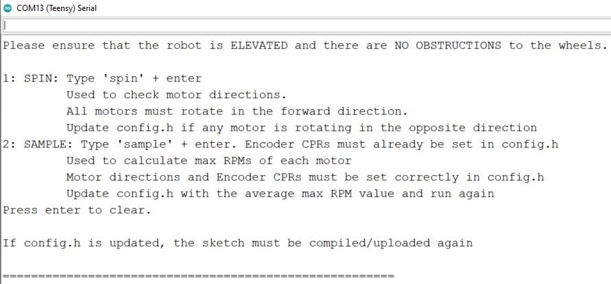
I kept the original structure the same, the serial monitor is used to select from two options: spin or sample. In each option, the motor is spun for a specified period of time, encoders are measured, and a report is generated based on some calculations. The following values are calculated and reported:
- The max RPM of the motors (at its max rated voltage)
- Deviation in the CPR values (calculated vs defined)
- Maximum velocities of the robot (at its operating voltage)
Max RPM
To get the max RPMs, first the encoder CPRs must be known. These are usually mentioned by the manufacturers, but these came with the motors in the same kit. So, I had to measure the CPRs myself. This was done by spinning the wheels (attached to the motors) by hand for exactly one revolution and measuring the encoder counts. One revolution can be measured by simply sticking a piece of tape to the motor and one to a reference surface. Then, align the wheel to the reference, and rotate till the tapes are aligned again. This should be done for all wheels and normally should be done a few times and then averaged. But you can also assume the CPR value after one accurate reading (without wheel slip or backlash) and round it to the nearest multiple of 4 (as it is a quadrature encoder). In my case, I repeated the experiment multiple times and averaged it to get an average CPR of 296 per motor. This value can be filled in the configuration file.
Next, using the defined encoder readings and the sample time of 10 seconds, I first calculated the encoder counts per second, which I could then extrapolate to counts per minute. Then using the defined CPR values, I got to the revolutions per minute (RPM). Since the motors are programmed to rotate at max PWM during the spin sequence, the calculated RPMs are the max RPMs of each motor. However, these are not the max RPMs the motors can achieve at its max rated voltage. The motors are rated at 12V and are operating at 9V, so the calculated max RPM is actually scaled down. The calibration sketch uses these values (defined in the configuration) to calculate the max rated RPMs of each motor. Now, since only one max RPM constant is used for all the motors, the calculated RPMs are averaged. According to the generated report, the motor is rated at around 176 RPMs at 12V, which results in around 132 RPMs at 9V.
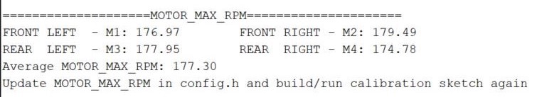
This number can however be made more accurate by increasing the MAX_RPM value in the configuration and running the sample sequence again. This will result in a change in the reported values. This is because the maximum RPM is calculated using the CPR values, which are not entirely accurate in the first place. This is a chicken and egg problem, since the CPR values are in turn dependent on the max RPM of the motors. However by repeating this experiment of increasing the MAX_RPM value in steps, the reported RPM of the motor will eventually converge to one value. This is the actual max RPM rating of the motors, and if increased in configuration, will not cause the reported value to change. The final value for the max RPM can be seen in the image below, averaged and rounded to 180 RPMs at 12V, which results in 135 RPMs at 9V.
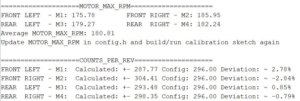
CPR (measured vs defined)
Once the max RPM rating of the motor is known, it needs to be defined in the configuration and the sample sequence must be run again after re-compiling. This time, the CPRs can be correctly calculated like in linorobot2_hardware and now we can compare it with the CPRs defined in the configuration. In the report I also added print commands to display the deviation of the measured CPR from the defined value. As can be seen in the image below, there is certainly some difference between the measured and defined CPRs.
As explained earlier, the CPR values are not defined by the manufacturer and need to be calculated by hand, but these are not entirely accurate. This is because of two reasons - human error (and some guesstimation during the measurement), and the fact that the max RPM is averaged. Since the motors do not rotate at the same speed, some precision is lost. So, the CPRs definitely need to be re-defined in the configuration, but since the max RPM is averaged, some deviation is still expected.
I first needed the correct (average) max RPM value, which converged to 180 in the previous step. Using the MAX_RPM value from the previous step (which converged to 180) in the configuration file, I get the following results:
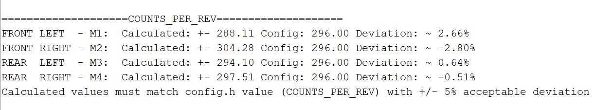
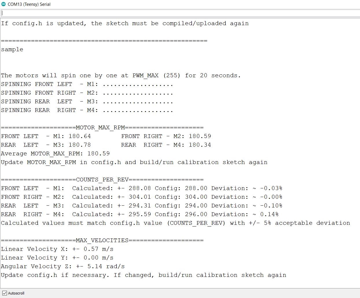
To confirm everything, I repeated the experiment one more time with the converged max RPM and CPR values, and updated the sample time to 20 seconds. On repeating the experiment, the values seem to change, but the deviation was minimal. In all the experiments, the deviation of the CPRs was reported to be less than 1% and the now that the correct CPR values were set, the max RPM values (of each motor) was always reported somewhere between 180 and 181. The following image shows the results. I consider them to be sufficient.
Testing
Finally, it was time to test, both the calibration sketch, and the main firmware. First, the calibration. I completely ignored the spin sequence since I do not need it. I am using Cytron MDD3A motor drivers that have handy buttons to test the motor directions. As I have already done the wiring, this has been defined and tested. I also used the encoder CPRs calculated for AKROS since the motors and encoders are the same.
I also have a voltage meter with a display, so I was able to measure the operating voltage at 9V. After updating them in the calibration configuration file, I simply ran the sample command twice - first to get the max RPM values, which was then updated to the configuration. The sequence was executed again, this time to verify maximum velocities of the robot.
Next, it was time to test the firmware. First, I updated the firmware configuration using the calibration config file (I need to have two as explained in the last post). To simplify things, I also merged the calibration sketch and the firmware in to the same branch. I had thought it would be easier to have the calibration sketch and the firmware in separate branches, but I was wrong. Having them in the same branch involves a lot of copied code, but it is much easier this way, and it works.
I also made a few changes to the firmware: first, I removed the namespace for simplicity, so the topics are now named /topic instead of akros2_base/topic.
Next, I added a brake function when the all the input velocities are 0 for longer than a specified amount of time (200 milliseconds in this case). This is to make the robot stop if the twist publisher is idle (publishing 0 values) or is not publishing any data because it has stopped working. However, in this case I noticed that when the robot was stopped, the previous error, it’s derivative and integral were all still stored in the PID objects. So, the next time the robot moved, the PID controller tried to correct for the old errors. So, I also added a resetAll() function in the PID library to set all error values to zero every time the robot was forced to brake.
One issue that I noticed working with teleop_twist_keyboard instead of my PS4 controller node, is that it does not publish any data when no keys are pressed. In my PS4 controller node, zero values are still published when no events are detected. So, the check to see if any data is published failed whenever I stopped pressing a key and the robot stopped suddenly while resetting all PID errors. So, I commented this check for now. I will remove the comment once I have my PS4 controller node set up in ROS2.
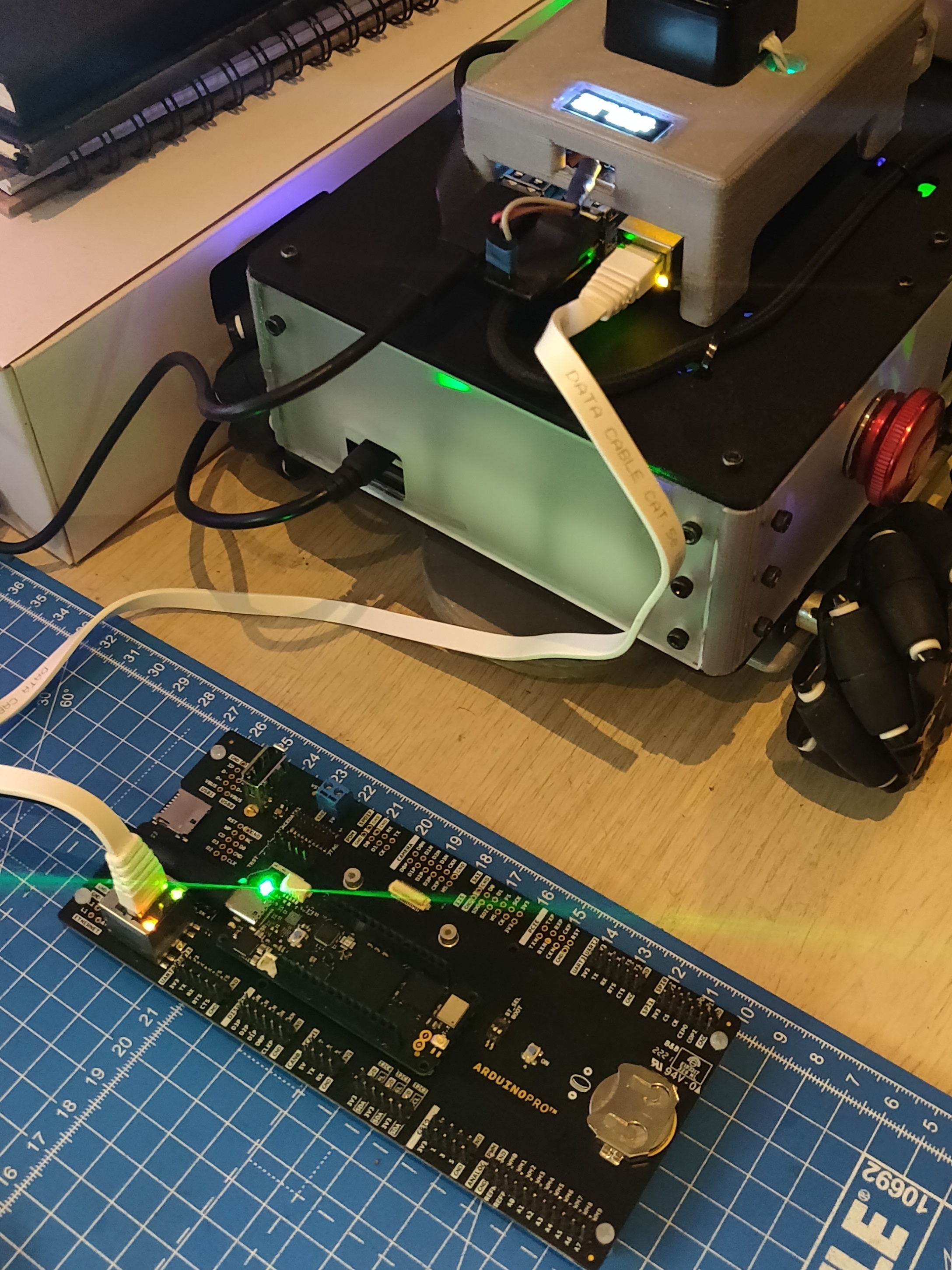
To test, I first opened four terminals and sourced ROS2 and the local installation in all of them. In the first terminal, I ran micro_ros_agent to connect to the Teensy using the following command:
ros2 run micro_ros_agent micro_ros_agent serial --dev /dev/ttyUSB_TEENSY
In the next one, I ran teleop_twist_keyboard to publish Twist messages using the following command:
ros2 run teleop_twist_keyboard teleop_twist_keyboard
I used the last two terminals to publish arbitrary modes from the command line, and to echo the published Twist messages for inspection. Finally, using teleop_twist_keyboard, I could start sending Twist messages to the robot. I also experimented by sending Mode messages using one of the terminals. The results were as expected, excellent for my first attempt, but the PID controller performance was slightly underwhelming as I will explain later.
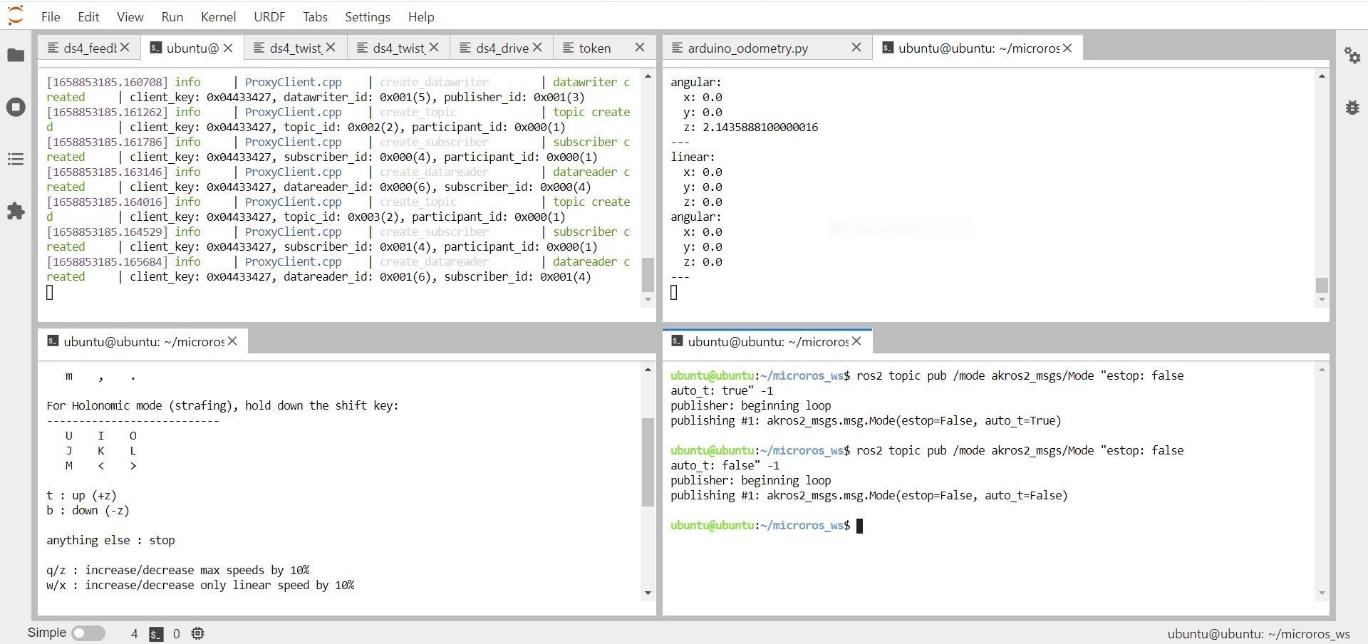
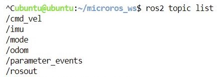
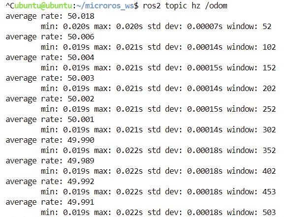
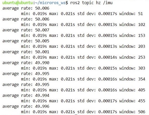
First, running ros2 topic list shows the list of topics. The micro-ROS client running on the Teensy subscribes to /cmd_vel and /mode from the micro-ROS agent. It then publishes /odom and /imu messages back to the micro-ROS agent.
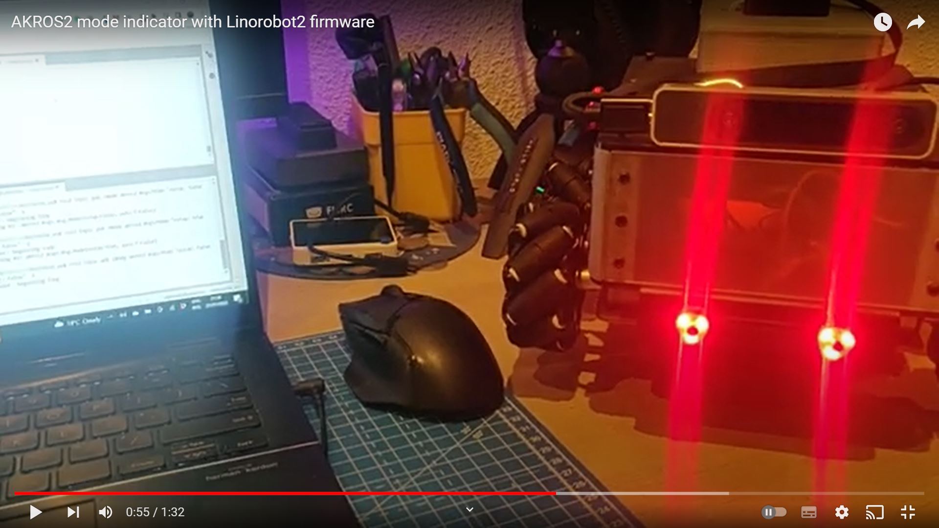
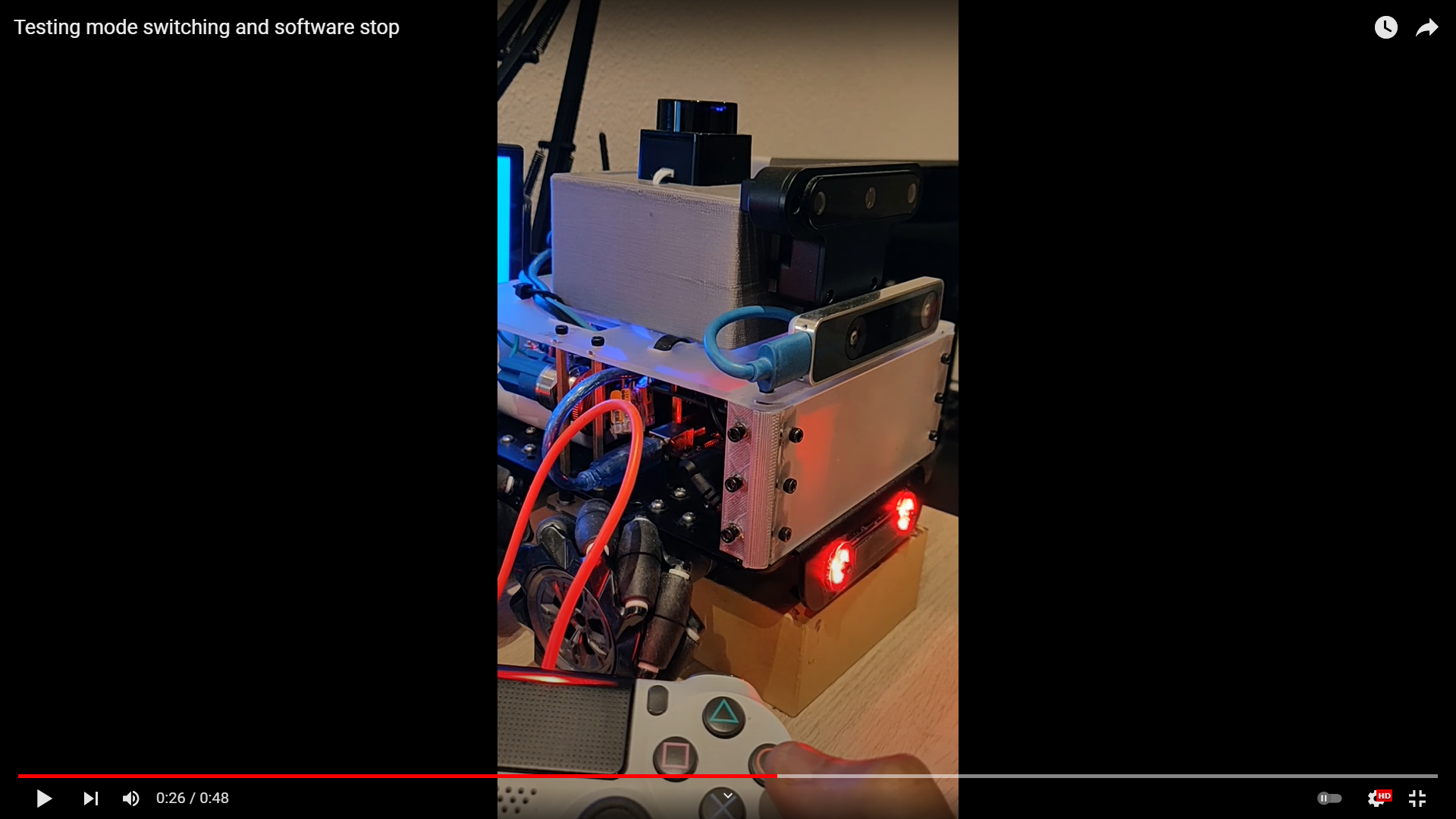
Next, using the ROS2 command line tools, I could then publish the /mode topic of akros2_msgs/Mode type to check the subscriber running on the Teensy. The colors should change according to the high level behavior defined in the firmware. The mode subscriber and the Neopixel indicator worked perfectly in my first attempt, much to my surprise. After setup, without the agent connected, the LEDs turned Cyan as expected. When the agent was connected, the LEDs turned to the color defined by the mode. When no mode was set, it turned to Green (teleop mode) by default. Blue was used for the autonomous mode, and Red was used to indicate when the emergency stop button is pressed.
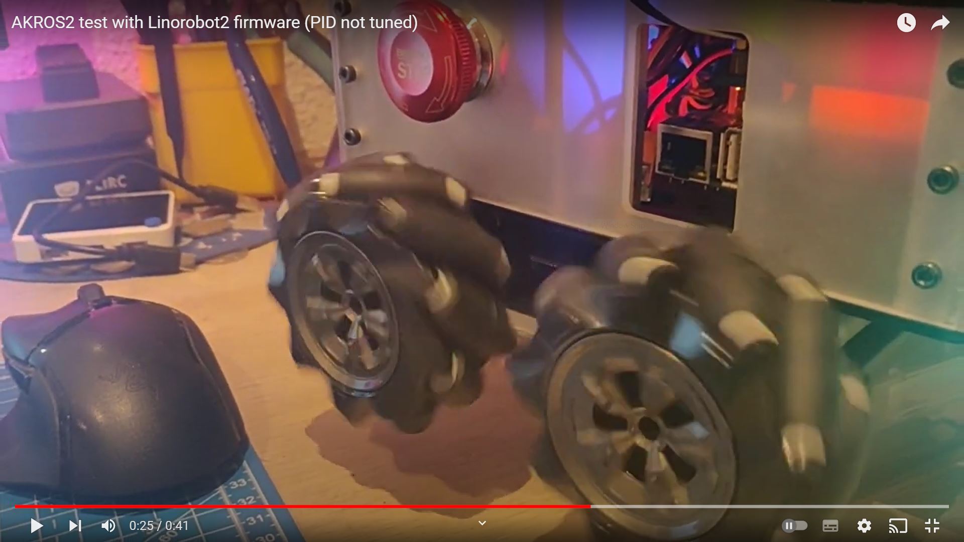
Now for the slightly underwhelming part. While the high level behavior worked as expected, the PID controller did not perform so well. Since I was using essentially the same config values as AKROS, the same PID values should have worked, or at least come close. Instead I observed an incredibly long rising time (between 3-7 seconds) to get the motor to it’s reference speed. Then I realized that while I was using the same PID algorithm, my outputs are in the range [0, PWM_MAX], where PWM_MAX = 255 (8 bit). With the Teensy, I can use 15 bit PWM, so PWM_MAX = (2^15 - 1) = 32767. The Linorobot2 also uses an output range of [-32767, +32767]. So, I need to scale my PID constants and re-tune the PID controller. I dislike tuning PID controllers (its time consuming, and the performance can always be better), so I’m currently reading about automatic tuning of PID controllers, so that I can implement an additional sequence in the calibration sketch.
Despite the PID issues, I am at least glad that everything else worked, I was especially worried that I had made major errors in the high level behavior with the modes. While I did not validate the received odometry or IMU messages, I was able to verify that these publishers were publishing data correctly and at the specified rate.
Other micro-ROS updates
I also spent some time on other micro-ROS things other than the AKROS2 firmware. Here are some updates:
Portenta Reconnection example
While I was working on the AKROS2 micro-ROS firmware, another developer managed to fix one of my open issues in the micro_ros_arduino repo. I had opened it a while ago when I was first trying the Reconnection example with the Arduino Portenta using UDP over Ethernet as the transport. I was unable to run that example as I had with serial transport, and I reported the issue. After the Teensy 4.1 Ethernet issue was fixed like I explained in in my last post, I was able to try the same example with the Teensy and it worked. So, I was able to isolate the issue to the Portenta. Since the fix was in the native ethernet transport, I tried it with both devices to verify and close the issue. With the transport now fixed, I definitely see some use for the Portenta in future projects, with Ethernet. So far, WiFi has been unreliable, and Serial hasn’t worked with large message sizes (like the VL53L5CX ToF PointCloud2 message).
RC Controller interface
I had been working on interfacing my FlySky FS-i6x RC controller with micro-ROS on the Teensy like I mentioned in an earlier post, and also the Arduino Nano RP2040, but faced some issues with the serial transport with both devices. I was able to decode IBus messages using Serial1 and publish micro-ROS messages using Serial in separate sketches, but not together. In the last few days, there has been some interest in this on Twitter by some other roboticists so I thought maybe I can pick it up again if there also others working on it. While I realized I do not need it with the AKROS2 robot, it is certainly very useful to have a RC controller receiver that can do some on-board mixing and publish a /cmd_vel message (Twist) from PWM values sent by a RC controller.
Next steps
I have a few more things before I can really finish with the micro-ROS firmware for AKROS2. First, of course I need to tune the PID controllers once again.
PID Tuning
I’ve spent some time thinking about how I want to tune the PID controllers. With AKROS, I used a very simplified version of the Ziegler-Nichols method like I have explain here. I used a simple sketch that I wrote on the Arduino IDE to run the motors, and used the Serial Plotter tool to plot the measured and required RPMs. I trialed it multiple times by changing the PID gains in my code, compiling it again and running it using the method I mentioned. This entire process was quite time-consuming.
For AKROS2, I want to make my life a bit easier. I want to be able to tune the PID controllers from the Raspberry Pi. First, I will also add another publisher, to publish the measured and required RPM of each motor. This way I would be able to plot and analyze the PID controller performance. In order to set the PID gains, there are two ways this can be done - First, by adding a subscriber to the micro-ROS firmware, and a publisher of the PID gains from the ROS2 host.
The second method is to set the PID gains as parameters from the ROS2 host. On the micro-ROS side, a parameter server will handle these parameters and when something changes, the PID gains would be updated. I wonder if this will work on the Teensy, considering I already have three publishers and two subscribers. The parameter server needs an additional five services and one optional publisher. I asked around on the micro-ROS Slack, and turns out it should be possible to do this, especially on the Teensy 4.1, so I intend to try it out.
I personally prefer the parameter server to the pub/sub option. This way I don’t need to constantly keep publishing PID gain values, and only set/unset them when needed. I should also be able to dump these parameters as a .yaml file and then load it in a launch file. These parameters in ROS2 along with the feedback publisher mentioned earlier, could be plotted and visualized for tuning the PID controllers. Like I mentioned in my last post, I have also wanted to implement the parameter server in some project, so this seems like the perfect opportunity.
Once I have the PID tuned, I can start with some additional features:
IMU Calibration and Odometry Fusion
First, I need to calibrate the MPU9250 IMU. It seems sufficiently calibrated right now, but to make sure it can be done for any IMU, I must add it to the calibration sketch as an additional sequence. Next, fusing it with Odometry. I don’t want to implement something complicated like an Extended Kalman Filter on the Teensy (although it would be nice), since I plan on doing it on the Raspberry Pi, where I can combine the odometry, the IMU measurements from the Teensy, and also the IMU measurements from the T265 to get a much more accurate position estimate. On the Teensy, I only want to use the IMU to detect if the robot is in motion. I can use this to update the odometry only when the robot is moving. If the robot is stationary and the wheel encoders are still measuring movement, then the robot is most likely stuck and odometry should not be updated. This simple filter improves odometry, and also makes the robot aware that it is stuck so that it can take corrective action such as reversing or by stopping the motors by setting the estop mode.
PS4 Controller interface
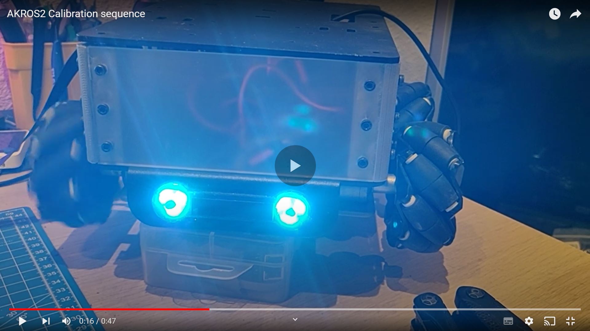
Finally, I want to port my PS4 controller node from ROS (akros_teleop) to ROS2 (akros2_teleop). It should not be very difficult as it is written in Python. The ROS implementation uses the ds4_driver package to read the status of the PS4 controller and its inputs and use it to run two scripts - a Twist publisher and a feedback publisher. The Twist publisher publishes on the /cmd_vel topic based on the status and a user-defined configuration file. The feedback publisher is used to set different modes based on button presses, which is published using the akros_msgs/Mode message type. It also publishes a feedback message used by ds4_driver to set the colors of the PS4 controller (based on the mode, an example in the video below), and also other features like the vibration motors on the controller. The ds4_driver package fortunately works for both ROS and ROS2, so I will be able to migrate to akros2_teleop without a lot of issues.
Once the PS4 controller interface is done, I will be able to uncomment all the commented parts in the firmware and test the entire firmware (without the odometry fusion) for the first time. Hopefully, should not take more than 2 weekends. *fingers crossed*